CN202493655U - Spiral bevel gear - Google Patents
Spiral bevel gear Download PDFInfo
- Publication number
- CN202493655U CN202493655U CN2012200019771U CN201220001977U CN202493655U CN 202493655 U CN202493655 U CN 202493655U CN 2012200019771 U CN2012200019771 U CN 2012200019771U CN 201220001977 U CN201220001977 U CN 201220001977U CN 202493655 U CN202493655 U CN 202493655U
- Authority
- CN
- China
- Prior art keywords
- bevel gear
- spiral bevel
- gear
- spiral
- shaft hole
- Prior art date
- Legal status (The legal status is an assumption and is not a legal conclusion. Google has not performed a legal analysis and makes no representation as to the accuracy of the status listed.)
- Expired - Fee Related
Links
- 238000009434 installation Methods 0.000 claims description 3
- 230000002787 reinforcement Effects 0.000 claims description 3
- 230000005540 biological transmission Effects 0.000 abstract description 11
- 230000003014 reinforcing effect Effects 0.000 abstract 1
- 230000009286 beneficial effect Effects 0.000 description 1
- 230000002950 deficient Effects 0.000 description 1
- 230000009347 mechanical transmission Effects 0.000 description 1
- 238000000034 method Methods 0.000 description 1
Images

Landscapes
- Gears, Cams (AREA)
- Gear Transmission (AREA)
Abstract
The utility model discloses a spiral bevel gear. The spiral bevel gear comprises a gear body. A mounting shaft hole is arranged in the center of the gear body. Spiral conical teeth are disposed on a circular surface which is disposed on one side surface of the gear body, wherein the shaft hole serves as the center of the circular surface. An included angle between a bus on the circular surface and the axis of the shaft hole is 30 degrees to 60 degrees. The shaft hole on the other side surface of the gear body is provided with a reinforcing convex ring extending outwardly. According to the spiral bevel gear, the spiral conical teeth are arranged on the side surface of the gear body and the included angle between a conical surface and the axis can be set specifically based on needs, thereby satisfying demands of the transmission included angle. Moreover, the spiral bevel gear enables the whole size of a transmission structure to be increased to make the occupation space of the overall structure small, and is high in transmission efficiency and high in bearing moment.
Description
Technical field
The utility model relates to the car wheel structure in the mechanical transmission, is specifically related to a kind of spiral bevel gear.
Background technique
The structural type of gear is varied; Like various forms such as spur wheel, angular gear, bevel gear, worm screws, the every field in being widely used in producing, living, this type gear cooperates drive mechanism generally to occupy than large space; Transmission efficiency is not very high; The transmission noise is bigger, and carrying moment is less, and generally can only be along parallel or vertical direction transferring power.Compact for some spaces, need higher transmission efficiency to reach occasion again than the large bearing capacity square, general gear configurations just can not be suitable for and special needs.
The model utility content
The purpose of the utility model is to overcome the defective that exists in the existing technology, provides a kind of simple in structure, and it is little to cooperate drive mechanism to take up space, stable drive, and efficient is high, and the transmission noise is low, carries the big spiral bevel gear of moment.
For realizing above-mentioned purpose; The technological scheme of the utility model is a kind of spiral bevel gear of design; Said spiral bevel gear comprises gear mass, is provided with installation axle hole at the center of said wheel body, it is characterized in that; Being provided with the axis hole in a side of said gear mass is to be distributed with spiral awl tooth on the belt face in the center of circle, and the angle between the bus on the said belt face and the axis of axis hole is 30 °~60 °.
Wherein optimized technical scheme is, is provided with outward extending reinforcement bulge loop at axis hole place, the another side of said gear mass.
The advantage and the beneficial effect of the utility model are: because this spiral bevel gear is provided with spiral awl tooth at the wheel body side surface; And the angle between the conical surface and the axis can carry out specific establishing as required; Thereby can satisfy the needs of transmission angle, and can add the overall dimensions of drive mechanism, it is little to make that its integral body takes up room; Transmission efficiency is higher, and carrying moment is big.
Description of drawings
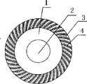
Fig. 1 is the Facad structure schematic representation of the utility model spiral bevel gear;
Fig. 2 is the plan view of Fig. 1.
Embodiment
Below in conjunction with accompanying drawing and embodiment, the embodiment of the utility model is further described.Following examples only are used for more clearly explaining the technological scheme of the utility model, and can not limit the protection domain of the utility model with this.
Like Fig. 1, shown in Figure 2; The utility model is a kind of spiral bevel gear; This spiral bevel gear comprises gear mass 1; Be provided with installation axle hole 2 at the center of said wheel body, being provided with axis hole 2 in a side of said gear mass 1 is to be distributed with spiral awl tooth 4 on the belt face 3 in the center of circle, and the angle between the bus on the said belt face 2 and the axis of axis hole 2 is 38 °.
Embodiment preferred is in the utility model, and axis hole 2 places are provided with outward extending reinforcement bulge loop 5 in the another side of said gear mass 1.
Because this spiral bevel gear is provided with spiral awl tooth at the wheel body side surface; And the angle between the conical surface and the axis can carry out specific establishing as required; Thereby can satisfy the needs of transmission angle, and can add the overall dimensions of drive mechanism, it is little to make that its integral body takes up room; Transmission efficiency is higher, and carrying moment is big.
The above only is the preferred implementation of the utility model; Should be understood that; For those skilled in the art; Under the prerequisite that does not break away from the utility model know-why, can also make some improvement and retouching, these improvement and retouching also should be regarded as the protection domain of the utility model.
Claims (2)
1. spiral bevel gear; Said spiral bevel gear comprises gear mass; Center at said wheel body is provided with installation axle hole; It is characterized in that being provided with the axis hole in a side of said gear mass is to be distributed with spiral awl tooth on the belt face in the center of circle, the angle between the bus on the said belt face and the axis of axis hole is 30 °~60 °.
2. spiral bevel gear according to claim 1 is characterized in that, is provided with outward extending reinforcement bulge loop at axis hole place, the another side of said gear mass.
Priority Applications (1)
| Application Number | Priority Date | Filing Date | Title |
|---|---|---|---|
| CN2012200019771U CN202493655U (en) | 2012-01-05 | 2012-01-05 | Spiral bevel gear |
Applications Claiming Priority (1)
| Application Number | Priority Date | Filing Date | Title |
|---|---|---|---|
| CN2012200019771U CN202493655U (en) | 2012-01-05 | 2012-01-05 | Spiral bevel gear |
Publications (1)
| Publication Number | Publication Date |
|---|---|
| CN202493655U true CN202493655U (en) | 2012-10-17 |
Family
ID=46999887
Family Applications (1)
| Application Number | Title | Priority Date | Filing Date |
|---|---|---|---|
| CN2012200019771U Expired - Fee Related CN202493655U (en) | 2012-01-05 | 2012-01-05 | Spiral bevel gear |
Country Status (1)
| Country | Link |
|---|---|
| CN (1) | CN202493655U (en) |
-
2012
- 2012-01-05 CN CN2012200019771U patent/CN202493655U/en not_active Expired - Fee Related
Similar Documents
| Publication | Publication Date | Title |
|---|---|---|
| CN201241938Y (en) | Speed reducer for disk feeding machine | |
| CN202493655U (en) | Spiral bevel gear | |
| CN202914243U (en) | Multipoint meshing type pitch-variable driving device and wind generating set adopting device | |
| CN201521602U (en) | High speed ratio four-stage parallel shaft hard gear surface gear speed reducer | |
| CN201944199U (en) | Two-stage worm speed reducer | |
| CN206468065U (en) | A kind of rotary type lugs and shutdown system | |
| CN203130319U (en) | High-power planetary retarding starter | |
| CN204334212U (en) | A kind of vibratile miniature gears reducing motor | |
| CN201078457Y (en) | Gear | |
| CN202780030U (en) | Novel cutting saw | |
| CN202756568U (en) | Gear with double-layer transmission teeth | |
| CN202327012U (en) | Portable speed reducer | |
| CN202251728U (en) | Gear box | |
| CN204300244U (en) | A kind of RV decelerator adopting wildhaber-novikov gear star reducing gear | |
| CN206168963U (en) | Tuber speed reducer | |
| CN202007864U (en) | Transmission mechanism for electric vehicles | |
| CN205371539U (en) | Hypoid gear | |
| CN202451705U (en) | Single-stage speed reducer | |
| CN202612586U (en) | Output shaft mechanism for planetary reduction gear | |
| CN204041881U (en) | Overturn platform main transmission double-stage worm gear worm reducer | |
| CN202176706U (en) | Bell-shaped planet carrier of a planet gear speed reducer of a mining dump truck | |
| CN103883721A (en) | Speed reducer of novel transmission structure | |
| CN201626311U (en) | Transmission mechanism of electric vehicle motor | |
| CN202829328U (en) | Novel environment-friendly driving device of electric single beam crane | |
| CN202542858U (en) | Bottom foundation ring for nitric acid absorption tower |
Legal Events
| Date | Code | Title | Description |
|---|---|---|---|
| C14 | Grant of patent or utility model | ||
| GR01 | Patent grant | ||
| C17 | Cessation of patent right | ||
| CF01 | Termination of patent right due to non-payment of annual fee |
Granted publication date: 20121017 Termination date: 20140105 |