CN202493490U - Wing type draught fan blade structure - Google Patents
Wing type draught fan blade structure Download PDFInfo
- Publication number
- CN202493490U CN202493490U CN2012200911542U CN201220091154U CN202493490U CN 202493490 U CN202493490 U CN 202493490U CN 2012200911542 U CN2012200911542 U CN 2012200911542U CN 201220091154 U CN201220091154 U CN 201220091154U CN 202493490 U CN202493490 U CN 202493490U
- Authority
- CN
- China
- Prior art keywords
- blade
- draught fan
- fan blade
- type draught
- blade structure
- Prior art date
- Legal status (The legal status is an assumption and is not a legal conclusion. Google has not performed a legal analysis and makes no representation as to the accuracy of the status listed.)
- Expired - Lifetime
Links
- 229910000831 Steel Inorganic materials 0.000 claims abstract description 7
- 239000010959 steel Substances 0.000 claims abstract description 7
- 239000006261 foam material Substances 0.000 claims abstract description 5
- 229910045601 alloy Inorganic materials 0.000 claims abstract description 4
- 239000000956 alloy Substances 0.000 claims abstract description 4
- 229910000851 Alloy steel Inorganic materials 0.000 claims abstract description 3
- 238000003466 welding Methods 0.000 claims description 10
- 238000005728 strengthening Methods 0.000 claims description 3
- 238000000034 method Methods 0.000 abstract description 2
- 229910001294 Reinforcing steel Inorganic materials 0.000 abstract 1
- 239000011324 bead Substances 0.000 abstract 1
- 239000000428 dust Substances 0.000 description 7
- 239000000945 filler Substances 0.000 description 4
- 238000013517 stratification Methods 0.000 description 4
- 230000006378 damage Effects 0.000 description 3
- 229920005830 Polyurethane Foam Polymers 0.000 description 1
- 208000034189 Sclerosis Diseases 0.000 description 1
- 238000005299 abrasion Methods 0.000 description 1
- 230000009286 beneficial effect Effects 0.000 description 1
- 238000010586 diagram Methods 0.000 description 1
- 230000000694 effects Effects 0.000 description 1
- 238000004519 manufacturing process Methods 0.000 description 1
- 239000000463 material Substances 0.000 description 1
- 238000012986 modification Methods 0.000 description 1
- 230000004048 modification Effects 0.000 description 1
- 239000011496 polyurethane foam Substances 0.000 description 1
- 230000002035 prolonged effect Effects 0.000 description 1
- 238000010079 rubber tapping Methods 0.000 description 1
Images
Landscapes
- Structures Of Non-Positive Displacement Pumps (AREA)
Abstract
Provided is a wind type draught fan blade structure. A blade is made of low alloy steel plates, an upper steel plate and a lower steel plate are welded to form an empty cavity, and a plurality of reinforcing steel plates are arranged inside the empty cavity of the blade along the inner radial direction in spot welded mode. Meanwhile, wear-resisting alloys are arranged on a windward surface of the blade in bead welded mode, and the empty cavity of the blade is filled with light foam materials. The wind type draught fan blade structure is simple in technology, convenient to process, and capable of effectively extending a wear through time of the wing type draught fan blade and prolonging the service life of the wing type draught fan blade.
Description
Technical field
The utility model relates to Fan Equipment, is specially a kind of wing formula fan blade structure.
Background technique
In a lot of commercial Application, in the actual fabrication of blower fan was used, wing formula blade was used by a large amount of; Be mainly used in the raising fan efficiency; Cut down the consumption of energy, and wing formula blade blower fan can be used for medium containing dust, and (dust loading is under 0.1~100g) the work condition environment, thereby applicable surface is wider.
Existing wing formula blade all is to utilize upper and lower two block plates welding to form cavity, and only can several stiffening plates of spot welding in the cavity, makes wing formula blade in use; Its mouth that facings the wind is worn out easily, and dust gets into blade interior easily in the medium, forms dust stratification; And dust stratification moves easily; And original balance of destruction draught fan impeller makes blower fan produce vibration, dislocation, and influences the normal device operation.
The model utility content
The technical problem that the utility model solved is to provide a kind of wing formula fan blade structure, in order to prolong the wing formula worn out time of blade; Solve the problem of the worn out back of wing formula blade dust stratification, destruction impeller balance.
The technical problem that the utility model solved adopts following technological scheme to realize:
A kind of wing formula fan blade structure utilizes Low Alloy Steel Plate to make blade, and the welding of upper and lower two block plates forms cavity, and at blade cavity inside several strengthening steel slabs of spot welding radially, simultaneously, the build-up wear-resistant alloy in the windward side of blade; And blade cavity inside filling lightweight foam material.
In the utility model, during the light filling foam material,, lightweight foam material is filled with the blade cavity from tapping from the perforate of blade lee face, treat after filler sclerosis or the curing hole to be shut.
Beneficial effect: the utility model has solved the problem of worn out easily, the worn out back of wing formula blade dust stratification destruction of balance well, has prolonged the working life of draught fan impeller effectively.
Description of drawings
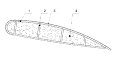
Fig. 1 is the generalized section of the utility model preferred embodiment.
Embodiment
For technological means, creation characteristic that the utility model is realized, reach purpose and be easy to understand understanding with effect, below in conjunction with concrete diagram, further set forth the utility model.
Referring to the preferred embodiment of a kind of wing formula fan blade structure of Fig. 1, in the present embodiment, utilize the Q345-B steel plate to make blade 1, four blocks of Q345-B steel plates of blade 1 inner spot welding are as strengthening steel slab 2.
As abrasion resistance alloy 3, blade 1 mouthful built-up welding thickness down with the wind is 6mm at blade 1 windward side built-up welding VAUTID-100, and all the other position built-up welding thickness are 3mm.
In the present embodiment; The internal cavities of selecting common polyurethane foam material to fill in the blade 1 as filler 4, from the lee face perforate of blade 1, each cavity is opened a hole; Filler 4 is filled with the blade cavity, and filler solidified after 24 hours shuts the perforate hole.
More than show and described the advantage of basic principle, major character and the utility model of the utility model.The technician of the industry should understand; The utility model is not restricted to the described embodiments; The principle of describing in the foregoing description and the specification that the utility model just is described; Under the prerequisite that does not break away from the utility model spirit and scope, the utility model also has various changes and modifications, and these variations and improvement all fall in the utility model scope that requires protection.The utility model requires protection domain to be defined by appending claims and equivalent thereof.
Claims (1)
1. a wing formula fan blade structure is characterized in that, utilizes Low Alloy Steel Plate to make blade, and the welding of upper and lower two block plates forms cavity, and at blade cavity inside several strengthening steel slabs of spot welding radially, simultaneously, the build-up wear-resistant alloy in the windward side of blade; Simultaneously, also be filled with lightweight foam material at the blade cavity inside.
Priority Applications (1)
| Application Number | Priority Date | Filing Date | Title |
|---|---|---|---|
| CN2012200911542U CN202493490U (en) | 2012-03-13 | 2012-03-13 | Wing type draught fan blade structure |
Applications Claiming Priority (1)
| Application Number | Priority Date | Filing Date | Title |
|---|---|---|---|
| CN2012200911542U CN202493490U (en) | 2012-03-13 | 2012-03-13 | Wing type draught fan blade structure |
Publications (1)
| Publication Number | Publication Date |
|---|---|
| CN202493490U true CN202493490U (en) | 2012-10-17 |
Family
ID=46999723
Family Applications (1)
| Application Number | Title | Priority Date | Filing Date |
|---|---|---|---|
| CN2012200911542U Expired - Lifetime CN202493490U (en) | 2012-03-13 | 2012-03-13 | Wing type draught fan blade structure |
Country Status (1)
| Country | Link |
|---|---|
| CN (1) | CN202493490U (en) |
Cited By (5)
| Publication number | Priority date | Publication date | Assignee | Title |
|---|---|---|---|---|
| CN105298913A (en) * | 2015-11-27 | 2016-02-03 | 卧龙电气南阳防爆集团股份有限公司 | Blade of axial flow fan and manufacturing method of blade |
| CN105332949A (en) * | 2015-11-27 | 2016-02-17 | 卧龙电气南阳防爆集团股份有限公司 | Steel blade of axial flow fan and integral forming technique of blade shells of steel blade |
| CN107781217A (en) * | 2017-12-03 | 2018-03-09 | 山西巨龙风机有限公司 | A kind of corrosion-resistant steel blade |
| CN112658607A (en) * | 2020-12-15 | 2021-04-16 | 赣州乾屹铭金属材料有限公司 | Production process of high-performance stirring blade |
| CN114367783A (en) * | 2022-01-10 | 2022-04-19 | 广东韶钢松山股份有限公司 | Maintenance method for fan vibration |
-
2012
- 2012-03-13 CN CN2012200911542U patent/CN202493490U/en not_active Expired - Lifetime
Cited By (5)
| Publication number | Priority date | Publication date | Assignee | Title |
|---|---|---|---|---|
| CN105298913A (en) * | 2015-11-27 | 2016-02-03 | 卧龙电气南阳防爆集团股份有限公司 | Blade of axial flow fan and manufacturing method of blade |
| CN105332949A (en) * | 2015-11-27 | 2016-02-17 | 卧龙电气南阳防爆集团股份有限公司 | Steel blade of axial flow fan and integral forming technique of blade shells of steel blade |
| CN107781217A (en) * | 2017-12-03 | 2018-03-09 | 山西巨龙风机有限公司 | A kind of corrosion-resistant steel blade |
| CN112658607A (en) * | 2020-12-15 | 2021-04-16 | 赣州乾屹铭金属材料有限公司 | Production process of high-performance stirring blade |
| CN114367783A (en) * | 2022-01-10 | 2022-04-19 | 广东韶钢松山股份有限公司 | Maintenance method for fan vibration |
Similar Documents
| Publication | Publication Date | Title |
|---|---|---|
| CN202493490U (en) | Wing type draught fan blade structure | |
| CN211713938U (en) | Protector of water conservancy water and electricity side slope | |
| CN103203266B (en) | Composite stepped wear-resistant lining plate | |
| CN113802989B (en) | Ultra-high working layer involute nozzle impregnated diamond drill bit and preparation method thereof | |
| CN204307667U (en) | One can assemble sand machine thrower head processed | |
| CN114033181A (en) | Pouring equipment for building | |
| CN109126998A (en) | A kind of adjustable crusher structure and the sand making machine comprising the mechanism | |
| CN202689951U (en) | Detachable geological drill bit | |
| CN205532306U (en) | Colliery is steel style PDC directional bit for directional drilling in pit | |
| CN204051785U (en) | A kind of sand machine thrower head processed | |
| CN208467248U (en) | A kind of ladle tank bottom working lining distributed architecture | |
| CN203620700U (en) | Crushing mechanism of vertical compound crusher | |
| CN204935911U (en) | Concrete powder storage hopper | |
| CN204220212U (en) | A kind of ladder type head wearing piece for hammer head of hammer crusher | |
| CN205839835U (en) | A kind of scraper bowl of open coal mine wheel loader | |
| CN217988960U (en) | A double-shaft mixer blade | |
| CN202083212U (en) | Split iron protector for mouth of rotary kiln | |
| CN206816248U (en) | A kind of higher Shearer Helical Drum of reliability | |
| CN109837892A (en) | Pile foundation prosthetic device | |
| CN206279575U (en) | A side plate reinforced bucket | |
| CN202273709U (en) | Wear-resisting chute of scraper loader | |
| CN220953619U (en) | High wear-resisting scraper bowl of excavator | |
| CN222863388U (en) | Hammer structure of mining crusher | |
| CN207030153U (en) | A kind of transporting chute | |
| CN203196698U (en) | Composite stepped wear-resisting lining plate |
Legal Events
| Date | Code | Title | Description |
|---|---|---|---|
| C14 | Grant of patent or utility model | ||
| GR01 | Patent grant | ||
| CX01 | Expiry of patent term | ||
| CX01 | Expiry of patent term |
Granted publication date: 20121017 |