CN202493317U - Exhaust and pollution discharge silencer for internal-combustion engine - Google Patents
Exhaust and pollution discharge silencer for internal-combustion engine Download PDFInfo
- Publication number
- CN202493317U CN202493317U CN2012200681165U CN201220068116U CN202493317U CN 202493317 U CN202493317 U CN 202493317U CN 2012200681165 U CN2012200681165 U CN 2012200681165U CN 201220068116 U CN201220068116 U CN 201220068116U CN 202493317 U CN202493317 U CN 202493317U
- Authority
- CN
- China
- Prior art keywords
- chamber
- pipe
- housing
- drain pipe
- engine exhaust
- Prior art date
- Legal status (The legal status is an assumption and is not a legal conclusion. Google has not performed a legal analysis and makes no representation as to the accuracy of the status listed.)
- Expired - Fee Related
Links
- 238000002485 combustion reaction Methods 0.000 title abstract description 8
- 230000003584 silencer Effects 0.000 title abstract 3
- 230000030279 gene silencing Effects 0.000 claims description 17
- 239000011148 porous material Substances 0.000 claims description 9
- 238000007789 sealing Methods 0.000 claims description 8
- 210000005239 tubule Anatomy 0.000 claims description 8
- 239000011358 absorbing material Substances 0.000 claims description 6
- 238000005192 partition Methods 0.000 claims description 6
- 230000001743 silencing effect Effects 0.000 abstract 1
- 239000000428 dust Substances 0.000 description 4
- 238000005516 engineering process Methods 0.000 description 3
- 230000003139 buffering effect Effects 0.000 description 2
- 230000000694 effects Effects 0.000 description 2
- 230000008030 elimination Effects 0.000 description 2
- 238000003379 elimination reaction Methods 0.000 description 2
- 238000000034 method Methods 0.000 description 2
- 230000000087 stabilizing effect Effects 0.000 description 2
- 230000009286 beneficial effect Effects 0.000 description 1
- 230000002950 deficient Effects 0.000 description 1
- 238000002474 experimental method Methods 0.000 description 1
- 238000012986 modification Methods 0.000 description 1
- 230000004048 modification Effects 0.000 description 1
- 230000010349 pulsation Effects 0.000 description 1
- 239000007921 spray Substances 0.000 description 1
- 239000002912 waste gas Substances 0.000 description 1
Images


Landscapes
- Exhaust Silencers (AREA)
Abstract
The utility model discloses an exhaust and pollution discharge silencer for an internal-combustion engine, which comprises a housing (9), wherein the front end and the rear end of the housing (9) are respectively connected with an inlet pipe (1) and an exhaust pipe (3), a discharge pipe (11) is arranged in an inner cavity of the housing (9); the discharge pipe (11) sequentially comprises a reducing pipe (11a), a throat pipe (11b) and an increasing pipe (11c) from front to rear; a small drain pipe (10) capable of being connected with an air filter is arranged in the discharge pipe (11); and an outlet of the small drain pipe (10) is positioned on the throat pipe (11b). The exhaust and pollution discharge silencer has better silencing effect, and is capable of prolonging the service life of the air filter, increasing power of the internal-combustion engine, and reducing oil consumption of the internal-combustion engine.
Description
Technical field
The utility model relates to a kind of silencing apparatus, particularly relates to a kind of silencing apparatus that can remove internal combustion engine exhaust noise.
Background technique
In the existing technology, air cleaner for internal combustion engine will accumulate a large amount of dusts after using a period of time, and this will influence the usability of air-strainer, the oil consumption of increasing combustion engine.And the silencing apparatus of conduct and the adjacent setting of air-strainer then only plays noise elimination, is difficult to the dust sucking-off with air-strainer.
Therefore those skilled in the art are devoted to develop a kind of I. C. engine exhaust blowdown silencing apparatus that can remove the air-strainer dust.
The model utility content
Because the above-mentioned defective of existing technology, the utility model technical problem to be solved provides a kind of I. C. engine exhaust blowdown silencing apparatus that can remove the air-strainer dust.
For realizing above-mentioned purpose, the utility model provides a kind of I. C. engine exhaust blowdown silencing apparatus, comprises housing; The rear and front end of said housing is connected with suction tude and outlet pipe respectively; Be provided with drain pipe in the inner chamber of said housing; Said drain pipe comprises reducing pipe, trunnion and increaser from front to back successively; Be provided with the blowdown tubule that can be connected in the said drain pipe with air-strainer; The outlet of said blowdown tubule is positioned at said trunnion place.
For absorbing the noise that the drain pipe place produces, corresponding said drain pipe place is provided with sound-absorbing material in the said housing.
For reducing air flow resistance, the front portion of said drain pipe is connected with the ingress pipe of uniform internal diameter; The rear portion of said drain pipe is connected with the delivery line of uniform internal diameter.
Preferable, be arranged at intervals with first dividing plate, second partition and the 3rd dividing plate in the said housing; First dividing plate, second partition and the 3rd dividing plate are divided into first chamber, second chamber, the 3rd chamber and the 4th chamber successively with the inner chamber of said housing; Said suction tude inserts in said first chamber; Said outlet pipe is picked out by said the 4th chamber; Said ingress pipe and drain pipe are arranged in said second chamber; Said delivery line is arranged in said the 3rd chamber; Said sound-absorbing material is filled in said second chamber; Said ingress pipe, drain pipe and delivery line are communicated with said first chamber and the 3rd chamber; Said the 3rd chamber is communicated with through intervalve with the 4th chamber; Said outlet pipe and intervalve are the structure of front end sealing, tail end opening, and pipe shaft is provided with pore.
For improving the noise elimination effect, each is unequal for the volume of said first chamber, second chamber, the 3rd chamber and the 4th chamber.
Preferable, said suction tude is the structure of both ends open, from the front end access of said first chamber.
Preferable, said suction tude is the structure of front opening, tail end sealing, and pipe shaft is provided with pore; Said suction tude inserts from the side of said first chamber.
Preferable, the front end of said housing is provided with front cover, and the rear end is provided with rear end cover.
The beneficial effect of the utility model is: the utlity model has the effect of eliminating the noise preferably, and can prolong the life-span of air-strainer, improve the power of motor, reduce the oil consumption of motor.
Description of drawings
Fig. 1 is the utility model embodiment 1 a structural representation.
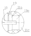
Fig. 2 is the partial enlarged drawing at I place among Fig. 1.
Fig. 3 is the utility model embodiment 2 a structural representation.
Embodiment
Below in conjunction with accompanying drawing and embodiment the utility model is described further.
Embodiment 1: as depicted in figs. 1 and 2, a kind of I. C. engine exhaust blowdown silencing apparatus comprises housing 9, and the rear and front end of housing 9 is connected with suction tude 1 and outlet pipe 3 respectively.The upper reaches with air-flow are that front end, downstream are the rear end, and the front end of housing 9 is provided with front cover 4, and the rear end is provided with rear end cover 5.
Be arranged at intervals with first dividing plate 6, second partition 7 and the 3rd dividing plate 8, the first dividing plates 6, second partition 7 and the 3rd dividing plate 8 in the housing 9 inner chamber of housing 9 is divided into first chamber 13, second chamber 14, the 3rd chamber 15 and the 4th chamber 16 successively.Each is unequal for the volume of first chamber 13, second chamber 14, the 3rd chamber 15 and the 4th chamber 16.
Suction tude 1 is the structure of both ends open, from the front end access of first chamber 13; Outlet pipe 3 is the structure of front end sealing, tail end opening, and pipe shaft is provided with a plurality of pores 12, and outlet pipe 3 is picked out by the 4th chamber 16.
Be provided with drain pipe 11 in second chamber 14, drain pipe 11 comprises reducing pipe 11a, trunnion 11b and increaser 11c from front to back successively.Be provided with the blowdown tubule 10 that can be connected with air-strainer in the drain pipe 11, the outlet of blowdown tubule 10 is positioned at trunnion 11b place.
The front portion of drain pipe 11 is connected with the ingress pipe 19 of uniform internal diameter, and the rear portion of drain pipe 11 is connected with the delivery line 18 of uniform internal diameter.Ingress pipe 19 all is positioned at second chamber 14 with drain pipe 11, and delivery line 18 is positioned at the 3rd chamber 15, so ingress pipe 19, drain pipe 11 and delivery line 18 are communicated with first chamber 13 and the 3rd chamber 15.
The 3rd chamber 15 is communicated with through intervalve 2 with the 4th chamber 16, and intervalve 2 is the structure of front end sealing, tail end opening, and pipe shaft is provided with pore 12.
Be filled with sound-absorbing material 17 in second chamber 14.
During silencing apparatus work, suction tude 1 is linked to each other with internal-combustion engine, blowdown tubule 10 links to each other with air-strainer.Therefore the high temperature of engine emission, at a high speed, the waste gas of high pulsation gets in first chamber 13 from suction tude 1; Get into the 3rd chamber 15 through ingress pipe 19, drain pipe 11 and delivery line 18; Get into the 4th chamber 16 through intervalve 2 then, discharge silencing apparatus from outlet pipe 3 at last.After air-flow got into the 3rd chamber 15 and the 4th chamber 16, a big strand air-flow was divided into some strands of little airflows by pore, and the moving direction of air-flow is changed 90 °, thereby impelled air-flow and sound wave flow point to leave, and therefore noise was weakened.
After air-flow got into reducing pipe 11a, the flow section of air-flow was more and more littler, and the speed of air-flow is increasing with generation degree of vacuum, reached maximum to trunnion 11b place.Because the outlet of blowdown tubule 10 is positioned at trunnion 10b place; Therefore under action of pressure, the laying dust in the air-strainer will be by sucking-off, and flowing in the increaser 11c with air-flow; Get into the 3rd chamber 15 through delivery line 18 then, after outlet pipe 3 enter in the atmosphere.
Because during engine exhaust process trunnion 11b, airspeed is very high, will produce regenerated noise, therefore sound-absorbing material 17 is set in second chamber, to eliminate middle and high frequency regenerated noise.
On the other hand; Because each is unequal for the volume of first chamber 13, the 3rd chamber 15 and the 4th chamber 16; The degree of therefore air-flow expansion in each chamber, deceleration, buffering and voltage stabilizing also has nothing in common with each other; Therefore can eliminate the noise of different frequency, the air-flow of pulsing at a high speed is adjusted into more stable low speed flow, get into atmosphere at last.
Embodiment 2: as shown in Figure 3, the structure of present embodiment and embodiment 1 are basic identical, and different is that suction tude 1 is the structure of front opening, tail end sealing, and pipe shaft is provided with pore; Suction tude 1 inserts from the side of first chamber 13.
The working principle of present embodiment and embodiment 1 are basic identical, but since the front opening of suction tude 1, the tail end sealing; Therefore air-flow can only spray from the pore on the suction tude 1; The air motion direction changes 90 °, and air-flow is become some shallow bids from a big share reform, and air-flow gets into ingress pipe 19 after overexpansion, deceleration, buffering and voltage stabilizing; Therefore, the engine air flow noise is tentatively reduced.
More than describe the preferred embodiment of the utility model in detail.Should be appreciated that those of ordinary skill in the art need not creative work and just can make many modifications and variation according to the design of the utility model.Therefore, all technician in the art according to the design of the utility model on the basis of existing technology through the available technological scheme of logical analysis, reasoning, or a limited experiment, all should be in determined protection domain by claims.
Claims (7)
1. an I. C. engine exhaust blowdown silencing apparatus comprises housing (9); The rear and front end of said housing (9) is connected with suction tude (1) and outlet pipe (3) respectively; It is characterized in that: be provided with drain pipe (11) in the inner chamber of said housing (9); Said drain pipe (11) comprises reducing pipe (11a), trunnion (11b) and increaser (11c) from front to back successively; Be provided with the blowdown tubule (10) that can be connected in the said drain pipe (11) with air-strainer; The outlet of said blowdown tubule (10) is positioned at said trunnion (11b) and locates.
2. I. C. engine exhaust blowdown silencing apparatus as claimed in claim 1 is characterized in that: corresponding said drain pipe (11) locates to be provided with sound-absorbing material (17) in the said housing (9).
3. I. C. engine exhaust blowdown silencing apparatus as claimed in claim 1 is characterized in that: the front portion of said drain pipe (11) is connected with the ingress pipe (19) of uniform internal diameter; The rear portion of said drain pipe (11) is connected with the delivery line (18) of uniform internal diameter.
4. I. C. engine exhaust blowdown silencing apparatus as claimed in claim 3 is characterized in that: be arranged at intervals with first dividing plate (6), second partition (7) and the 3rd dividing plate (8) in the said housing (9); First dividing plate (6), second partition (7) and the 3rd dividing plate (8) are divided into first chamber (13), second chamber (14), the 3rd chamber (15) and the 4th chamber (16) successively with the inner chamber of said housing (9);
Said suction tude (1) inserts in said first chamber (13); Said outlet pipe (3) is picked out by said the 4th chamber (16);
Said ingress pipe (19) and drain pipe (11) are arranged in said second chamber (14); Said delivery line (18) is arranged in said the 3rd chamber (15); Be filled with sound-absorbing material (17) in said second chamber (14);
Said ingress pipe (19), drain pipe (11) and delivery line (18) are communicated with said first chamber (13) and the 3rd chamber (15); Said the 3rd chamber (15) is communicated with through intervalve (2) with the 4th chamber (16);
Said outlet pipe (3) and intervalve (2) are the structure of front end sealing, tail end opening, and pipe shaft is provided with pore (12).
5. I. C. engine exhaust blowdown silencing apparatus as claimed in claim 4 is characterized in that: each is unequal for the volume of said first chamber (13), second chamber (14), the 3rd chamber (15) and the 4th chamber (16).
6. like claim 4 or 5 described I. C. engine exhaust blowdown silencing apparatuss, it is characterized in that: said suction tude (1) is the structure of both ends open, from the front end access of said first chamber (13).
7. like claim 4 or 5 described I. C. engine exhaust blowdown silencing apparatuss, it is characterized in that: said suction tude (1) is the structure of front opening, tail end sealing, and pipe shaft is provided with pore; Said suction tude (1) inserts from the side of said first chamber (13).
Priority Applications (1)
| Application Number | Priority Date | Filing Date | Title |
|---|---|---|---|
| CN2012200681165U CN202493317U (en) | 2012-02-28 | 2012-02-28 | Exhaust and pollution discharge silencer for internal-combustion engine |
Applications Claiming Priority (1)
| Application Number | Priority Date | Filing Date | Title |
|---|---|---|---|
| CN2012200681165U CN202493317U (en) | 2012-02-28 | 2012-02-28 | Exhaust and pollution discharge silencer for internal-combustion engine |
Publications (1)
| Publication Number | Publication Date |
|---|---|
| CN202493317U true CN202493317U (en) | 2012-10-17 |
Family
ID=46999550
Family Applications (1)
| Application Number | Title | Priority Date | Filing Date |
|---|---|---|---|
| CN2012200681165U Expired - Fee Related CN202493317U (en) | 2012-02-28 | 2012-02-28 | Exhaust and pollution discharge silencer for internal-combustion engine |
Country Status (1)
| Country | Link |
|---|---|
| CN (1) | CN202493317U (en) |
Cited By (2)
| Publication number | Priority date | Publication date | Assignee | Title |
|---|---|---|---|---|
| CN112160817A (en) * | 2020-10-09 | 2021-01-01 | 黄山天之都环保科技有限公司 | Infrared suppression system is administered to underground works mobile power station tail gas |
| CN115523009A (en) * | 2022-09-26 | 2022-12-27 | 奇瑞汽车股份有限公司 | A multi-reflection special-shaped composite muffler |
-
2012
- 2012-02-28 CN CN2012200681165U patent/CN202493317U/en not_active Expired - Fee Related
Cited By (2)
| Publication number | Priority date | Publication date | Assignee | Title |
|---|---|---|---|---|
| CN112160817A (en) * | 2020-10-09 | 2021-01-01 | 黄山天之都环保科技有限公司 | Infrared suppression system is administered to underground works mobile power station tail gas |
| CN115523009A (en) * | 2022-09-26 | 2022-12-27 | 奇瑞汽车股份有限公司 | A multi-reflection special-shaped composite muffler |
Similar Documents
| Publication | Publication Date | Title |
|---|---|---|
| CN204436529U (en) | A kind of diesel generating set smoke-ejecting pipe silencing apparatus | |
| CN202493317U (en) | Exhaust and pollution discharge silencer for internal-combustion engine | |
| CN201184226Y (en) | Automobile energy-saving silencer | |
| CN202789020U (en) | Exhaust muffler for automobile | |
| CN202209317U (en) | Middle cavity structure of silencing device of filtering silencer | |
| CN202431337U (en) | Silencer of 8kW gasoline engine generator | |
| CN202493327U (en) | Pollution-discharging and gas-exhausting silencer | |
| CN202768127U (en) | Automobile silencer | |
| CN221074405U (en) | Spark-extinguishing muffler with cleanable function | |
| CN203067061U (en) | Gasoline engine exhaust silencer | |
| CN102221019A (en) | Hollow cavity structure of filter silencer sound elimination device | |
| CN201003493Y (en) | Wind screen type silencer | |
| CN203189081U (en) | Rotary exhaust silencer for motorcycle | |
| CN204716339U (en) | The silencing apparatus of compact type exhaust | |
| CN201521328U (en) | Dual-exhaust port silencer of diesel generator | |
| CN213510796U (en) | Silencer structure with aftertreatment | |
| CN205154328U (en) | A silencer for taking two exhaust structure of T engine | |
| CN2474732Y (en) | Silencer | |
| CN204877596U (en) | Muffler is used in automobile engine exhaust | |
| CN204476509U (en) | Prevent the silencing apparatus that carbon deposit Mars sprays | |
| CN2871858Y (en) | Silencer for automobile | |
| RU106657U1 (en) | ICE NOISE MUFFLER | |
| RU2220783C1 (en) | Air cleaner of gas-turbine drive | |
| CN109339921B (en) | Automobile exhaust muffler | |
| CN202209199U (en) | Noise silencer |
Legal Events
| Date | Code | Title | Description |
|---|---|---|---|
| C14 | Grant of patent or utility model | ||
| GR01 | Patent grant | ||
| CF01 | Termination of patent right due to non-payment of annual fee |
Granted publication date: 20121017 Termination date: 20150228 |
|
| EXPY | Termination of patent right or utility model |