CN202492958U - Roof truss node gusset plate and lightweight steel structure thereof - Google Patents
Roof truss node gusset plate and lightweight steel structure thereof Download PDFInfo
- Publication number
- CN202492958U CN202492958U CN2011205605479U CN201120560547U CN202492958U CN 202492958 U CN202492958 U CN 202492958U CN 2011205605479 U CN2011205605479 U CN 2011205605479U CN 201120560547 U CN201120560547 U CN 201120560547U CN 202492958 U CN202492958 U CN 202492958U
- Authority
- CN
- China
- Prior art keywords
- punching press
- press beading
- beading
- roof truss
- junction plate
- Prior art date
- Legal status (The legal status is an assumption and is not a legal conclusion. Google has not performed a legal analysis and makes no representation as to the accuracy of the status listed.)
- Expired - Fee Related
Links
- 229910000831 Steel Inorganic materials 0.000 title claims abstract description 25
- 239000010959 steel Substances 0.000 title claims abstract description 25
- 238000004080 punching Methods 0.000 claims abstract description 125
- 239000002184 metal Substances 0.000 claims abstract description 18
- 238000010276 construction Methods 0.000 claims description 11
- 239000011888 foil Substances 0.000 claims description 10
- 238000010079 rubber tapping Methods 0.000 claims description 10
- 238000005452 bending Methods 0.000 claims description 8
- 238000005098 hot rolling Methods 0.000 claims description 3
- 238000000465 moulding Methods 0.000 claims description 3
- 238000003466 welding Methods 0.000 description 5
- 239000000203 mixture Substances 0.000 description 2
- 239000007787 solid Substances 0.000 description 2
- 238000010586 diagram Methods 0.000 description 1
- 238000005516 engineering process Methods 0.000 description 1
- 238000002474 experimental method Methods 0.000 description 1
- 238000009434 installation Methods 0.000 description 1
Images


Landscapes
- Joining Of Building Structures In Genera (AREA)
Abstract
The utility model relates to a roof truss node gusset plate and a lightweight steel structure thereof, wherein the plate body of the roof truss node gusset plate is formed by punching a metal thin-wall plate and comprises a plate type integral connecting piece comprising a chord member connecting plate and a web member connecting plate; a punched pressing rib protruding towards the front surface of the metal thin-wall plate and not communicated with the edge of the plate body is arranged on the plate body; the punched pressing rib is composed of a transverse punched pressing rib, a left vertical punched pressing rib, a right vertical punched pressing rib, an upper arched punched pressing rib and a lower arched punched pressing rib; the transverse punched pressing rib is arranged on the chord member connecting plate; the left vertical punched pressing rib is distributed from the chord member connecting plate and the web member connecting plate; and the right vertical punched pressing rib is distributed from the chord member connecting plate and the web member connecting plate. According to the utility model, the bearing capacities and the rigidities of the connecting plates are greatly increased; therefore, the connecting plates become more firm; in particular, in the event of being stressed by force in a plurality of directions, the connecting plates are difficult to bend or deform.
Description
Technical field
The utility model relates to a kind of node and connects metal sheet and truss, and particularly a kind of stamping forming node connects metal sheet and truss.
Background technology
Characteristics such as the light gauge cold-formed steel shape truss has reasonable stress, light weight, anti-seismic performance is good, easy to make, speed of application is fast have obtained using widely in recent years in lightgage steel joist system dwelling house, office building and medium and small span building.Rod member in the tradition light gauge cold-formed steel shape truss generally is that 6mm is thick in interior side (square) type pipe, pipe, angle steel and channel-section steel etc., and the connected mode of rod member is welding, bolt connection or self-tapping screw connection etc.
Welding is a kind of direct connected mode between the light gauge cold-formed steel shape truss member.Although this connected mode bearing capacity greatly, does not need contact panel, the welding job amount is big, take a lot of work, and because steel truss rod member cross section is thinner, welding operation is inconvenience very, and welding quality is difficult to be guaranteed.
Adopting bolt to connect through gusset plate is the another kind of connected mode between the light gauge cold-formed steel shape truss member.The layout of the shape of each gusset plate and bolt hole can be decided according to the internal force of rod member around the node on the truss; Generally all inequality, this brings very burden for the making and the processing of truss, and the perforated area of bolt hole is too big; It is too many that the cross section weakens, so use few.
Linking to each other through lightweight steel construction connector and self-tapping screw is the third connected mode between the rod member in the cold bending thin wall type lightweight steel construction.Present lightweight steel construction connector generally is designed to flat board, no punching press beading, and no flange, and not general; In addition, also there are some metallic interconnects to have the punching press beading, but solid inadequately, especially when receiving the power of a plurality of directions, take place easily curvedly to split or be out of shape, so need improvement.
The utility model content
The purpose of the utility model provides a kind of roof truss node buckle and lightweight steel construction thereof, solves to be difficult for the technical problem that connection, bearing capacity and rigidity needs further improve between traditional clod wash Steel Thin-Wall truss member.
For realizing above-mentioned purpose; The utility model adopts following technical scheme: a kind of roof truss node buckle; Its plate body is a tabular whole connector that is stamped to form and is included chord member junction plate and web member junction plate by the metal foil wallboard; The edge, the left and right sides of said web member junction plate is spill; And the edge of spill has perpendicular to the plate face and to the crooked circular-arc flange of metal thin-wall backboard face; Plate body is provided with the punching press beading to positive protruding drum of metal foil wallboard and obstructed plate body edge, also is provided with screw hole on the plate body, it is characterized in that: said punching press beading by horizontal punching press beading, the vertical punching press beading in a left side, right vertical punching press beading, go up arc punching press beading and arc lower punching press beading is formed.
Said horizontal punching press beading is arranged on the chord member junction plate.
The vertical punching press beading in a said left side distributes from chord member junction plate to web member junction plate; A left side is the top and horizontal punching press beading cross of punching press beading vertically, and the bottom of the vertical punching press beading in a left side bends towards the left lower end of web member junction plate, is 60 ° of angles with horizontal punching press beading.
The vertical punching press beading in the said right side distributes from chord member junction plate to web member junction plate; The top of right vertically punching press beading and horizontal punching press beading cross, the bottom of right vertical punching press beading bends, is 60 ° of angles with horizontal punching press beading towards the bottom righthand side of web member junction plate.
Said upward arc punching press beading and arc lower punching press beading are arranged on the web member junction plate and are connected between the vertical punching press beading of the vertical punching press beading in a left side and the right side, and last arc punching press beading is bent upwards, the downwarping of arc lower punching press beading.
The said bending place T word of going up the vertical punching press beading of a left end and a left side of arc punching press beading intersects, and the right-hand member of last arc punching press beading intersects with the bending place T word of the vertical punching press beading in the right side.
The left end of said arc lower punching press beading intersects with the vertical punching press beading T word in a left side, and the right-hand member of arc lower punching press beading intersects with right vertical punching press beading T word.
Said metal foil wallboard two on the angle at right angles or arc chord angle.
The cross section of said punching press beading is a circular arc.
The width of said punching press beading is 5mm~10mm, and the degree of depth is 2mm~5mm.
The two ends of the two ends of said horizontal punching press beading, the vertical punching press beading in a left side and the two ends of right vertical punching press beading all with the edge of plate body 5mm~20mm apart.
A kind of lightweight steel construction of using said roof truss node buckle; It is characterized in that: by a chord member; The 60 ° of web members in a left side; The 60 ° of web members in a right side; And the symmetrical double-edged two blocks of roof truss node buckles composition that is clipped in the connected node place of chord member, the 60 ° of web members in a left side and right 60 ° of web members, the chord member junction plate on the said roof truss node buckle is fixedly connected with chord member through self-tapping screw, and the web member junction plate on the roof truss node buckle passes through 60 ° of web members of a self-tapping screw and a left side, right 60 ° of web members fixed are connected.
The cross section of said chord member, the 60 ° of web members in a left side, right 60 ° of web members is rectangle, C shape or the hat steel pipe of clod wash, hot rolling or alternate manner moulding.
Compared with prior art, the utlity model has following characteristics: the utility model provides a kind of roof truss node buckle, is stamped to form through mould by the metal foil wallboard, and versatility is good; Be designed with the punching press beading of particular form on the roof truss node buckle, bearing capacity and rigidity that this has improved itself greatly make the more solid of its change, and can bear more multi-direction and bigger power; Open aperture on the junction plate, can make things convenient for self-tapping screw to connect; Connect band arc limit, spot bight, make profile more attractive in appearance.
Be designed with specific punching press beading on the said roof truss node buckle; These punching press beadings connect the integral body that forms a closure each other on plate body, improved the bearing capacity and the rigidity of node buckle greatly, the experiment proof; Adopt the roof truss node buckle of this punching press beading; Its stress performance obviously is superior to existing various node buckle, and especially when receiving the power of a plurality of directions, it can not take place curvedly to split or be out of shape easily; In addition, bearing capacity and the stability of having used the lightweight steel construction of said roof truss node buckle also are greatly improved.
Circular-arc flange on the said roof truss node buckle promptly can spacing web member, guarantees the accurate connection of web member, has improved the bearing capacity and the rigidity of roof truss node buckle again, has overcome that traditional node buckle versatility is poor, the weakness of interchangeability difference.Roof truss node buckle connects through self-tapping screw; Overcome that traditional connected mode makes that workload is big, bearing capacity and rigidity is low, the shortcoming of difficult quality guarantee; Its shape be connected hole through mould one time punching molded; Making and installation are all very convenient, can be widely used in the connection between the cold bending thin wall metal truss rod member.
Description of drawings
Below in conjunction with accompanying drawing the utility model is done further detailed explanation.
Fig. 1 is a schematic perspective view of seeing roof truss node buckle from the front.
Fig. 2 is a schematic perspective view of seeing roof truss node buckle from the back side.
Fig. 3 is a schematic perspective view of having used a Pin framework of the utility model.
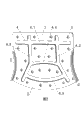
Fig. 4 is the enlarged diagram of the junction of roof truss and lattice column in the Pin framework.
Reference numeral: 1-chord member junction plate, 2-web member junction plate, the circular-arc flange of 3-, 4-punching press beading, the horizontal punching press beading of 4.1-, the vertical punching press beading in a 4.2-left side, the right vertical punching press beading of 4.3-, the last arc punching press of 4.4-beading, 4.5-arc lower punching press beading, 5-screw hole, 6-chord member, the 60 ° of web members in a 7-left side, the right 60 ° of web members of 8-, 9-lattice column, 10-roof truss.
The specific embodiment
Referring to Fig. 1, shown in Figure 2; This roof truss node buckle; Its plate body is a tabular whole connector that is stamped to form and is included chord member junction plate 1 and web member junction plate 2 by the metal foil wallboard, and the edge, the left and right sides of said web member junction plate 2 is spill, and the edge of spill has perpendicular to the plate face and to the crooked circular-arc flange 3 of metal thin-wall backboard face; Plate body is provided with the punching press beading 4 to positive protruding drum of metal foil wallboard and obstructed plate body edge, also is provided with screw hole 5 on the plate body.
Said punching press beading 4 by horizontal punching press beading 4.1, the vertical punching press beading 4.2 in a left side, right vertical punching press beading 4.3, go up arc punching press beading 4.4 and arc lower punching press beading 4.5 is formed; Said horizontal punching press beading 4.1 is arranged on the chord member junction plate 1.
The vertical punching press beading 4.2 in a said left side distributes from chord member junction plate 1 to web member junction plate 2; A left side is the top and horizontal punching press beading 4.1 crosses of punching press beading 4.2 vertically, and the bottom of the vertical punching press beading 4.2 in a left side bends towards the left lower end of web member junction plate 2, is 60 ° of angles with horizontal punching press beading 4.1.
The vertical punching press beading 4.3 in the said right side distributes from chord member junction plate 1 to web member junction plate 2; The top of right vertically punching press beading 4.3 and horizontal punching press beading 4.1 crosses, the bottom of right vertical punching press beading 4.3 bends, is 60 ° of angles with horizontal punching press beading 4.1 towards the bottom righthand side of web member junction plate 2.
Said upward arc punching press beading 4.4 and arc lower punching press beading 4.5 are arranged on the web member junction plate 2 and are connected between the vertical punching press beading 4.3 of the vertical punching press beading 4.2 in a left side and the right side; Last arc punching press beading 4.4 is bent upwards, 4.5 downwarpings of arc lower punching press beading.In the present embodiment, the said bending place T word of going up the vertical punching press beading 4.2 of a left end and a left side of arc punching press beading 4.4 intersects, and the right-hand member of last arc punching press beading 4.4 intersects with the bending place T word of the vertical punching press beading 4.3 in the right side.The left end of said arc lower punching press beading 4.5 intersects with the vertical punching press beading 4.2T word in a left side, and the right-hand member of arc lower punching press beading 4.5 intersects with right vertical punching press beading 4.3T word.
Said metal foil wallboard two on the angle at right angles or arc chord angle.The cross section of said punching press beading is a circular arc, and the width of punching press beading is 5mm~10mm, and the degree of depth is 2mm~5mm.The two ends of the two ends of said horizontal punching press beading 4.1, the vertical punching press beading 4.2 in a left side and the two ends of right vertical punching press beading 4.3 all with the edge of plate body 5mm~20mm apart.
Referring to Fig. 3, Fig. 4; It is a Pin framework; This Pin framework includes lattice column 9 and roof truss 10, includes the lightweight steel construction of using said roof truss node buckle in the said roof truss 10, the lightweight steel construction of the said roof truss node of this application buckle; By a chord member 6; The 60 ° of web members 8 in 7, right sides of 60 ° of web members, a left side, and symmetry is clipped in double-edged two blocks of roof truss node buckles composition at the connected node place of chord member 6, the 60 ° of web members 7 in a left side and right 60 ° of web members 8; Chord member junction plate 1 on the said roof truss node buckle is fixedly connected with chord member 6 through self-tapping screw, and the web member junction plate 2 on the roof truss node buckle is fixedly connected through 60 ° of web members 7 of a self-tapping screw and a left side, right 60 ° of web members 8.The cross section of said chord member 6, the 60 ° of web members 7 in a left side, right 60 ° of web members 8 can be rectangle, C shape or the hat steel pipe of clod wash, hot rolling or alternate manner moulding; In the present embodiment, chord member 6, the 60 ° of web members 7 in a left side and right 60 ° of web members 8 all are thin-walled side's (square) shape pipes.
Claims (9)
1. roof truss node buckle; Its plate body is a tabular whole connector that is stamped to form and is included chord member junction plate (1) and web member junction plate (2) by the metal foil wallboard; The edge, the left and right sides of said web member junction plate (2) is spill; And the edge of spill has perpendicular to the plate face and to the crooked circular-arc flange (3) of metal thin-wall backboard face; Plate body is provided with the punching press beading (4) to positive protruding drum of metal foil wallboard and obstructed plate body edge; Also be provided with screw hole (5) on the plate body, it is characterized in that: said punching press beading (4) by horizontal punching press beading (4.1), the vertical punching press beading (4.2) in a left side, right vertical punching press beading (4.3), go up arc punching press beading (4.4) and arc lower punching press beading (4.5) is formed;
Said horizontal punching press beading (4.1) is arranged on the chord member junction plate (1);
The vertical punching press beading in a said left side (4.2) distributes from chord member junction plate (1) to web member junction plate (2); A left side is the top and horizontal punching press beading (4.1) cross of punching press beading (4.2) vertically, and the bottom of the vertical punching press beading (4.2) in a left side bends towards the left lower end of web member junction plate (2), is 60 ° of angles with horizontal punching press beading (4.1);
The vertical punching press beading in the said right side (4.3) distributes from chord member junction plate (1) to web member junction plate (2); The top of right vertically punching press beading (4.3) and horizontal punching press beading (4.1) cross, the bottom of right vertical punching press beading (4.3) bends, is 60 ° of angles with horizontal punching press beading (4.1) towards the bottom righthand side of web member junction plate (2);
Said upward arc punching press beading (4.4) and arc lower punching press beading (4.5) are arranged on web member junction plate (2) and go up and be connected the vertical punching press beading (4.2) in a left side and right vertically between the punching press beading (4.3); Last arc punching press beading (4.4) is bent upwards, arc lower punching press beading (4.5) downwarping.
2. roof truss node buckle according to claim 1; It is characterized in that: the said bending place T word of going up the vertical punching press beading (4.2) of a left end and a left side of arc punching press beading (4.4) intersects, and the right-hand member of last arc punching press beading (4.4) intersects with the bending place T word of the vertical punching press beading (4.3) in the right side.
3. roof truss node buckle according to claim 2; It is characterized in that: the left end of said arc lower punching press beading (4.5) intersects with vertical punching press beading (4.2) the T word in a left side, and the right-hand member of arc lower punching press beading (4.5) intersects with right vertical punching press beading (4.3) T word.
4. roof truss node buckle according to claim 1 is characterized in that: said metal foil wallboard two on the angle at right angles or arc chord angle.
5. roof truss node buckle according to claim 1 is characterized in that: the cross section of said punching press beading is a circular arc.
6. roof truss node buckle according to claim 1 is characterized in that: the width of said punching press beading is 5mm~10mm, and the degree of depth is 2mm~5mm.
7. roof truss node buckle according to claim 1 is characterized in that: the two ends of the two ends of said horizontal punching press beading (4.1), the vertical punching press beading (4.2) in a left side and the two ends of right vertical punching press beading (4.3) all with the edge of plate body 5mm~20mm apart.
8. an application rights requires the lightweight steel construction of any said roof truss node buckle of 1-7; It is characterized in that: by a chord member (6); The 60 ° of web members in a left side (7); The 60 ° of web members in the right side (8); And double-edged two blocks of roof truss node buckles that symmetry is clipped in the connected node place of chord member (6), a left side 60 ° of web members (7) and right 60 ° of web members (8) form, and the chord member junction plate (1) on the said roof truss node buckle is fixedly connected with chord member (6) through self-tapping screw, and the web member junction plate (2) on the roof truss node buckle passes through self-tapping screw and is fixedly connected with left 60 ° of web members (7), the 60 ° of web members in the right side (8).
9. the lightweight steel construction of the said roof truss node of application according to claim 8 buckle is characterized in that: the cross section of said chord member (6), a left side 60 ° of web members (7), right 60 ° of web members (8) is rectangle, C shape or the hat steel pipe of clod wash, hot rolling or alternate manner moulding.
Priority Applications (1)
| Application Number | Priority Date | Filing Date | Title |
|---|---|---|---|
| CN2011205605479U CN202492958U (en) | 2011-12-29 | 2011-12-29 | Roof truss node gusset plate and lightweight steel structure thereof |
Applications Claiming Priority (1)
| Application Number | Priority Date | Filing Date | Title |
|---|---|---|---|
| CN2011205605479U CN202492958U (en) | 2011-12-29 | 2011-12-29 | Roof truss node gusset plate and lightweight steel structure thereof |
Publications (1)
| Publication Number | Publication Date |
|---|---|
| CN202492958U true CN202492958U (en) | 2012-10-17 |
Family
ID=46999193
Family Applications (1)
| Application Number | Title | Priority Date | Filing Date |
|---|---|---|---|
| CN2011205605479U Expired - Fee Related CN202492958U (en) | 2011-12-29 | 2011-12-29 | Roof truss node gusset plate and lightweight steel structure thereof |
Country Status (1)
| Country | Link |
|---|---|
| CN (1) | CN202492958U (en) |
-
2011
- 2011-12-29 CN CN2011205605479U patent/CN202492958U/en not_active Expired - Fee Related
Similar Documents
| Publication | Publication Date | Title |
|---|---|---|
| CN101200965B (en) | Stamping formed metal connection board and girders | |
| CN201165725Y (en) | Punch forming metal connecting board and girders | |
| CN102561510A (en) | Factory assembled latticed light steel structure and manufacturing method thereof | |
| CN202157420U (en) | 45-degree beam column combination fastener and lightweight steel structure thereof | |
| CN102359187A (en) | 45 degrees beam and column combined buckling piece and light steel structure | |
| CN202492958U (en) | Roof truss node gusset plate and lightweight steel structure thereof | |
| CN102535713A (en) | Roof ridge gusset and light steel structure thereof | |
| CN102535740A (en) | Roof truss node buckle plate and lightweight steel structure thereof | |
| CN202492932U (en) | Lattice column gusset plate and lightweight steel construction thereof | |
| CN202492956U (en) | Ridge node gusset plate and lightweight steel structure thereof | |
| CN202492933U (en) | T-shaped gusset plate and light steel structure thereof | |
| CN102322102B (en) | Beam-passing fastener and lightweight steel construction for connecting upper layer and lower layer | |
| CN202492928U (en) | Factory assembly type lattice lightweight steel construction | |
| CN102535641A (en) | Lattice column gusset and light steel structure thereof | |
| CN201391018Y (en) | Upper-lower layer punching connecting piece and lightweight steel structure thereof | |
| CN201310148Y (en) | Building special type light steel pipe and connecting piece thereof | |
| CN201460022U (en) | Cold bending thin-wall welded steel truss purline | |
| CN202222204U (en) | Support structure for greenhouse frame | |
| CN217183213U (en) | Photovoltaic support purlin holds in palm structure and photovoltaic support | |
| CN106049747A (en) | Honeycomb profiled steel sheet-concrete precast slab | |
| CN202152490U (en) | Beam penetrating fastener connecting upper layer and lower layer and light steel structure of beam penetrating fastener | |
| CN204059969U (en) | U-shaped holder | |
| CN201391516Y (en) | Connecting piece with lightweight steel structure | |
| CN202164712U (en) | Trimmer fastener and light steel structure thereof | |
| CN202152511U (en) | Plastrum-testudinis-shaped lightweight steel column connecting fastener and lightweight steel construction thereof |
Legal Events
| Date | Code | Title | Description |
|---|---|---|---|
| C14 | Grant of patent or utility model | ||
| GR01 | Patent grant | ||
| C17 | Cessation of patent right | ||
| CF01 | Termination of patent right due to non-payment of annual fee |
Granted publication date: 20121017 Termination date: 20131229 |