CN202492879U - Loading machine counter weight device - Google Patents
Loading machine counter weight device Download PDFInfo
- Publication number
- CN202492879U CN202492879U CN2012200734374U CN201220073437U CN202492879U CN 202492879 U CN202492879 U CN 202492879U CN 2012200734374 U CN2012200734374 U CN 2012200734374U CN 201220073437 U CN201220073437 U CN 201220073437U CN 202492879 U CN202492879 U CN 202492879U
- Authority
- CN
- China
- Prior art keywords
- counterweight
- counter weight
- loader
- weight device
- casting
- Prior art date
- Legal status (The legal status is an assumption and is not a legal conclusion. Google has not performed a legal analysis and makes no representation as to the accuracy of the status listed.)
- Expired - Fee Related
Links
- 238000005266 casting Methods 0.000 claims abstract description 17
- 239000007787 solid Substances 0.000 abstract description 2
- 238000009434 installation Methods 0.000 description 4
- 230000007704 transition Effects 0.000 description 3
- 239000004568 cement Substances 0.000 description 2
- 238000000034 method Methods 0.000 description 2
- 238000003466 welding Methods 0.000 description 2
- 230000007423 decrease Effects 0.000 description 1
- 230000005484 gravity Effects 0.000 description 1
- 238000011900 installation process Methods 0.000 description 1
- 238000004519 manufacturing process Methods 0.000 description 1
- 238000007789 sealing Methods 0.000 description 1
- 229910000679 solder Inorganic materials 0.000 description 1
Images


Landscapes
- Component Parts Of Construction Machinery (AREA)
Abstract
The utility model discloses a loading machine counter weight device. The loading machine counter weight device comprises two eudipleural independent counter weights, and each counter weight is integrated into a whole through casting. Front portions of the counter weights are provided with boss parts. When the counter weights are installed on a machine frame, the boss parts are pressed on a tail board of the machine frame. Therefore, stress of bolts is reduced, and level can be controlled at the same time after the counter weights are installed. A lamp screen and counter weight bodies are molded through casting at the same time, and the lamp screen is too solid to be damaged by falling objects. Meanwhile, through matching of a cambered surface design, the counter weights are beautiful in appearance, compact in outline and smooth in line.
Description
Technical field
The utility model is the loader technical field, particularly a kind of counter weight device that is installed on the loader.
Technical background
In order to guarantee loader when work complete machine rollover stability, need counterweight be installed at the afterbody of loader usually.Present counterweight form is divided integrated poured, monoblock cast and split casting form.Integral solder casting cement counterweight cost is low, but complex process, big, the bolt strained inequality of position of centre of gravity deviation, overall volume are big, the shortcoming that is prone to occur in the commissure crack.The monoblock cast volume is little, but the counterweight lines simple, be inconvenient to assemble.The loader taillight is installed in the lampshade on the counterweight more, and mostly lampshade is thin-slab structure, decreases distortion damage taillight thereby pounded by junk easily.Split type counterweight also exists taillight lampshade to be prone to be pounded damage by junk, and outward appearance is simple and because tailgate welding back distortion causes counterweight that excesssive gap between back and tailgate is installed, and the counterweight outward appearance is also simply stiff.
Summary of the invention
The utility model is big to existing counterweight welding casting cement complex process or casting difficulty; The thin plate lampshade on the counterweight and the technical problem of the flimsy shortcoming of taillight; Provide a kind of independent left and right two split type loader counter weight devices, lampshade directly and counter weight device be cast as one.
The technical scheme that the utility model adopts is:
A kind of loader counter weight device comprises the symmetrical left counterweight of independent casting, right counterweight, and each counterweight is equipped with the loader taillight lampshade with counterweight main body casting.Described loader taillight lampshade is cast as certain wall thickness, guarantees the intensity of lampshade, and can satisfy junk and pound to knock and do not cause the lampshade distortion, thus the protection light fixture.
Above-described counterweight is equipped with the convexity with counterweight main body casting.Said convexity contacts with back vehicle frame tailgate, prevents the inclination of counterweight in installation and use.
Above-described counterweight is provided with through hole, and described counterweight is passed through hole with bolt and is fixed in behind the loader on the vehicle frame.
Above-described counterweight is provided with the screwed hole of lifting usefulness, and when non-lifting state, described screwed hole seals with plug screw, can prevent that rainwater from getting into; The plug screw of when needs liftings counterweight, back-outing, the suspender of screwing on.
Above-described screwed hole is two.
Above-described loader taillight lampshade and counterweight main body connecting portion are cast as cambered surface.Lampshade and counterweight body adopt curvilinear flow line style cambered surface design transition, make the graceful simplicity generosity of counterweight appearance profile lines.
The advantage of the utility model:
1. the split-type design of counterweight, it is big, heavy to have solved existing counterweight monoblock cast difficulty, the problem that inconvenience is installed.
2. the utility model counterweight manufacturing process is simple, and lampshade is with the main body casting, and is solid reliable.The lampshade of existing design is often pounded the problem of knocking damage by junk when having solved loader work.
3. with the convex design of counterweight main body casting, the installation easily of counterweight can not only be realized, the inclination of counterweight in installation and use can also be prevented.
4. the design of screwed hole has alleviated the labour intensity of counterweight in installation process.
5. lampshade and counterweight body adopt curvilinear flow line style cambered surface design transition, make the graceful simplicity generosity of counterweight appearance profile lines.
Description of drawings
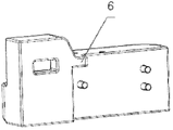
Fig. 1 is the loader counter weight device left side counterweight figure of the utility model.
Fig. 2 is the right counterweight figure of the loader counter weight device of the utility model.
Fig. 3 is the loader counter weight device left side counterweight rear elevation of the utility model.
Fig. 4 is the right counterweight rear elevation of the loader counter weight device of the utility model.
Among the figure:
Left side counterweight 1, bolt 2, right counterweight 3, plug screw 4, loader taillight lampshade 5, convexity 6, cambered surface 7,8.
The specific embodiment
Embodiment 1
A kind of loader counter weight device, the independent symmetrical left counterweight of casting (1), right counterweight (3), each counterweight is equipped with the loader taillight lampshade (5) with counterweight main body casting; Further be provided with through hole on each counterweight, bolt (2) passes through hole and can counterweight be fixed on behind the loader on the vehicle frame; Each counterweight further is provided with the screwed hole of lifting usefulness, and when non-lifting state, described screwed hole can prevent that rainwater from getting into, the plug screw of when needs lift by crane counterweight, back-outing, the suspender of screwing on plug screw (4) sealing.
Embodiment 2
With embodiment 1 different place be: on the basis of embodiment 1, further be equipped with the convexity of counterweight main body casting (6) in counterweight (1), (3).Said convexity (6) contacts with back vehicle frame tailgate, prevents the inclination of counterweight in installation and use.
With embodiment 2 different places be: on the basis of embodiment 2, further be cast as cambered surface (7,8) at loader taillight lampshade (5) and counterweight main body connecting portion.Lampshade and counterweight body adopt curvilinear flow line style cambered surface design transition, make the graceful simplicity generosity of counterweight appearance profile lines.
With embodiment 3 different places be: on the basis of embodiment 2, further be equipped with two screwed holes in counterweight (1), (3).
Claims (6)
1. a loader counter weight device comprises the symmetrical left counterweight of independent casting (1), right counterweight (3), it is characterized in that: each counterweight is equipped with the loader taillight lampshade (5) with counterweight main body casting.
2. loader counter weight device according to claim 1 is characterized in that: described counterweight (1), (3) are equipped with the convexity of counterweight main body casting (6).
3. loader counter weight device according to claim 1 and 2 is characterized in that: described counterweight is provided with through hole, and described counterweight is passed through hole with bolt (2) and is fixed in behind the loader on the vehicle frame.
4. loader counter weight device according to claim 3 is characterized in that: described counterweight is provided with the screwed hole of lifting usefulness, and when non-lifting state, described screwed hole seals with plug screw (4).
5. loader counter weight device according to claim 1 and 2 is characterized in that: described loader taillight lampshade (5) is cast as cambered surface (7,8) with counterweight main body connecting portion.
6. loader counter weight device according to claim 4 is characterized in that: described screwed hole is two.
Priority Applications (1)
| Application Number | Priority Date | Filing Date | Title |
|---|---|---|---|
| CN2012200734374U CN202492879U (en) | 2012-03-01 | 2012-03-01 | Loading machine counter weight device |
Applications Claiming Priority (1)
| Application Number | Priority Date | Filing Date | Title |
|---|---|---|---|
| CN2012200734374U CN202492879U (en) | 2012-03-01 | 2012-03-01 | Loading machine counter weight device |
Publications (1)
| Publication Number | Publication Date |
|---|---|
| CN202492879U true CN202492879U (en) | 2012-10-17 |
Family
ID=46999114
Family Applications (1)
| Application Number | Title | Priority Date | Filing Date |
|---|---|---|---|
| CN2012200734374U Expired - Fee Related CN202492879U (en) | 2012-03-01 | 2012-03-01 | Loading machine counter weight device |
Country Status (1)
| Country | Link |
|---|---|
| CN (1) | CN202492879U (en) |
-
2012
- 2012-03-01 CN CN2012200734374U patent/CN202492879U/en not_active Expired - Fee Related
Similar Documents
| Publication | Publication Date | Title |
|---|---|---|
| CN202492879U (en) | Loading machine counter weight device | |
| CN207808953U (en) | Automobile swing arm | |
| CN204824036U (en) | Electric fork -lift counter weight | |
| CN201329798Y (en) | Structure of engine suspending bracket | |
| CN207844947U (en) | A kind of chassis saddle weight | |
| CN203383251U (en) | Excavator boom and excavator | |
| CN202577431U (en) | Balance weight device of loader | |
| CN202379676U (en) | Forklift counter weight | |
| CN203637827U (en) | Aluminum along inclined strut plate of railway coal hopper car | |
| CN205240376U (en) | Self -discharging adds sand hopper | |
| CN202321939U (en) | Locomotive radiator hoisting structure | |
| CN207191957U (en) | A kind of steel scrap separative-clip type charging hopper | |
| CN204284262U (en) | A kind of high-strength light braking bottom board | |
| CN205132960U (en) | Perpendicular hydro -cylinder backing plate of mobile crane | |
| CN204150865U (en) | Elevator is other opens front sedan-chair wall | |
| CN218058368U (en) | Counter weight device and aerial work platform | |
| CN103693550B (en) | Vehicle side reversal hanger | |
| CN210889557U (en) | Heavy-load hydraulic cylinder fixing device | |
| CN202767148U (en) | Excavator seal plate convenient to check and maintain | |
| CN204818704U (en) | A gun platform assembly fixture charges | |
| CN204311357U (en) | A kind of connecting rod side plate | |
| CN203237993U (en) | Goods forking rack for loading and unloading goods | |
| CN201916821U (en) | Multifunctional LED lamp panel structure | |
| CN202132343U (en) | Anti-falling screw for screen window | |
| CN207962571U (en) | A kind of novel fabricated lamp stand |
Legal Events
| Date | Code | Title | Description |
|---|---|---|---|
| C14 | Grant of patent or utility model | ||
| GR01 | Patent grant | ||
| CF01 | Termination of patent right due to non-payment of annual fee |
Granted publication date: 20121017 Termination date: 20190301 |
|
| CF01 | Termination of patent right due to non-payment of annual fee |