CN202492790U - Orthotropic plate of steel box girder - Google Patents
Orthotropic plate of steel box girder Download PDFInfo
- Publication number
- CN202492790U CN202492790U CN2011205194698U CN201120519469U CN202492790U CN 202492790 U CN202492790 U CN 202492790U CN 2011205194698 U CN2011205194698 U CN 2011205194698U CN 201120519469 U CN201120519469 U CN 201120519469U CN 202492790 U CN202492790 U CN 202492790U
- Authority
- CN
- China
- Prior art keywords
- weld
- steel box
- rib
- plate
- rib plates
- Prior art date
- Legal status (The legal status is an assumption and is not a legal conclusion. Google has not performed a legal analysis and makes no representation as to the accuracy of the status listed.)
- Expired - Fee Related
Links
- 229910000831 Steel Inorganic materials 0.000 title claims abstract description 40
- 239000010959 steel Substances 0.000 title claims abstract description 40
- 230000002146 bilateral effect Effects 0.000 claims abstract description 12
- 238000003466 welding Methods 0.000 claims description 23
- 238000005336 cracking Methods 0.000 description 5
- 230000000694 effects Effects 0.000 description 5
- 208000037656 Respiratory Sounds Diseases 0.000 description 4
- 238000010276 construction Methods 0.000 description 4
- 238000005516 engineering process Methods 0.000 description 3
- 238000005452 bending Methods 0.000 description 2
- 230000003601 intercostal effect Effects 0.000 description 2
- 230000008602 contraction Effects 0.000 description 1
- 238000009826 distribution Methods 0.000 description 1
- 238000004519 manufacturing process Methods 0.000 description 1
- 230000004048 modification Effects 0.000 description 1
- 238000012986 modification Methods 0.000 description 1
- 238000000465 moulding Methods 0.000 description 1
- 238000002360 preparation method Methods 0.000 description 1
- 239000003755 preservative agent Substances 0.000 description 1
- 230000002335 preservative effect Effects 0.000 description 1
Images


Landscapes
- Arc Welding In General (AREA)
Abstract
The utility model discloses an orthotropic plate of a steel box girder. The orthotropic plate comprises a plurality of U shaped ribs and a panel of the steel box girder; wherein the U shaped ribs are formed by side rib plates and top rib plates and connected with the panel of the steel box girder by bilateral fillet welds. The structure of the U shaped ribs is improved, the unilateral fillet weld way on the connection position of the U shaped ribs and the panel is transferred to the contact fillet weld between the side rib plates and the top rib plates, so as to realize bilateral fillet weld connection, thereby improving the fatigue performance of the weld and reducing the weld failure risk. The contact fillet weld between the side rib plates and the top rib plates is far away from the panel, even though the filled weld is the unilateral fillet weld, the weld is not directly affected by wheel load, and has relatively low requirement for fatigue performance, thus the use requirement is also satisfied.
Description
Technical field
The utility model belongs to steel case beam manufacturing technology field, specifically is a kind of steel case beam orthotropic plate.
Background technology
Welded steel bridge just flourish, is striden rivers, bridge spanning the sea constantly builds up.Steel bridge is the above public building of design service life a century; And belong to and typically receive dynamic load load structure; Requirement to fatigue properties of welded joints is very strict, and in Longspan Bridge, steel case beam form is very general; Because of crackle appears in its panel construction U-shaped stiffening rib place weld seam easily in operation, the attachment weld fatigue behaviour of U-shaped rib and bridge deck receives much concern.
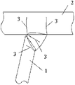
Because the U-shaped stiffening rib structure has excellent bending resistance and torsional property; Extensively receive steel bridge designer's welcome; Fig. 1 is the structural representation of steel case beam orthotropic plate, receives the restriction of its form of structure and size, at present; Only can be through single face welding and panel welding, the weld seam form is bevelled fillet weld.Under the effect of wheel load, the join domain of U-shaped rib-panel produces the outer moment of flexure of face, because the thickness of slab of panel and stiffening rib is all thinner relatively; Cause the skin bending stress of panel and floor bigger; One one of U-shaped rib root place's deformation is closed, and the stress concentration phenomenon is very obvious, in addition; General have bigger welding vestige stress here, thus cause the effect repeatedly of wheel load down fatigue crack possibly germinate with welding toe and expand at the higher root of weld of stress concentration degree.Fig. 2 is the crackle signal that the join domain of U-shaped rib-panel possibly occur, and crackle 3 mainly is to be caused by local buckling stress.
The utility model content
The purpose of the utility model provides a kind of steel case beam orthotropic plate that can effectively solve U-shaped rib and steel box beam and face weld cracking problem.
According to the utility model a kind of steel case beam orthotropic plate is provided, comprises:
U-shaped rib and steel box beam and face;
Said U-shaped rib is connected on the said steel box beam and face through the bilateral fillet weld.
Further, said U-shaped rib comprises:
Two side rib plates, top floor and some location-plates;
Some location-plates and two said side rib plate welding;
Said top floor and two said side rib plate top welding;
The bottom of two blocks of said side rib plates is connected on the said steel box beam and face through the bilateral fillet weld.
A kind of steel case beam orthotropic plate that the utility model provides; Through improvement to the U-shaped rib structure; The one-sided fillet weld form of U-shaped rib and panel junction is transferred in the witnessed corner weld seam of side plate rib and top board intercostal; Realize the connection of bilateral fillet weld, thereby improved the fatigue behaviour of its weld seam, reduce the weld cracking risk.And the witnessed corner weld seam between side rib plate and the top floor though be one-sided fillet weld, does not receive directly influencing of wheel weight away from panel zone, and is lower to the fatigue behaviour requirement, can satisfy instructions for use equally.
Description of drawings
Fig. 1 is the structural representation of a kind of steel case beam orthotropic plate in the prior art;
Fig. 2 is the crackle sketch map that the join domain of U-shaped rib-panel among Fig. 1 possibly occur;
The welding sketch map of location-plate and side rib plate in a kind of steel case beam orthotropic plated construction that Fig. 3 provides for the utility model embodiment;
The welding sketch map of side rib plate and steel box beam and face in a kind of steel case beam orthotropic plated construction that Fig. 4 provides for the utility model embodiment;
The welding sketch map of top floor and side rib plate in a kind of steel case beam orthotropic plated construction that Fig. 5 the utility model embodiment provides.
The specific embodiment
As shown in Figure 3, a kind of steel case beam orthotropic plate that the utility model provides comprises: plurality of U-shaped rib and steel box beam and face 2, wherein, the U-shaped rib comprises two blocks of side rib plates 4, some location-plates 5 and top floor 6.Some location-plates 5 and two side rib plate 4 welding; Top floor 6 and two side rib plate 4 tops welding; The bottom of two blocks of side rib plates 4 is connected on the steel box beam and face 2 through the bilateral fillet weld.
The preparation technology of the steel case beam orthotropic plate as shown in Figure 3 that the utility model provides comprises:
Step S1: as shown in Figure 3, earlier that two blocks of side rib plates 4 are fixing through six location-plates 5, specifically be that the fillet weld between location-plate 5 and the side rib plate 4 is welded.
Step S2: as shown in Figure 4, again two side rib plate 4 bottoms are welded on the steel box beam and face 2, adopt the bilateral fillet weld to connect.
Step S3: as shown in Figure 5, with top floor 6 two side rib plate 4 tops are linked together then, specifically be that the witnessed corner weld seam between top floor 6 and the side rib plate 4 is welded, whole U-shaped rib is fixed on the steel box beam and face 2.
The U-shaped rib is decomposed into three-lane road shape stiffening rib, connects by the witnessed corner weld seam, the substep erection welding, last assembly welding becomes " U-shaped rib ", reaches the stiffening effect of U-shaped rib, and " U-shaped rib " inner corners weld seam is realized the bilateral weldering with the welding of fillet welding dolly.
When U-shaped rib and 2 welding of steel box beam and face; U-shaped rib weld seam private side has the fillet weld load; Changing one-sided fillet weld is the bilateral fillet weld; Can change weld seam junction stress distribution, significantly slow down the stress concentration phenomenon of the U-shaped rib root of weld under the moment of flexure effect outside face, thereby effectively solve U-shaped rib and bridge deck weld cracking problem.
Steel case beam orthotropic plate by the utility model provides can not only be kept the unary form of structure of present steel box beam and face and put more energy into effect, and can effectively solve U-shaped rib and bridge deck weld cracking problem." location-plate 5 " can be used as inner membrance offside floor 4 and plays the role of positioning, and also do not receive U-shaped rib inner " location-plate 5 " influence during welding.The utility model adopts the U-shaped rib of assembling also to exempt the operation of making when having the U-shaped rib now that bends.Can spot welding be required to reduce in the inboard spot welding of U-shaped rib, improve the appearance forming of U-shaped rib weld seam.During welding, the witnessed corner weld seam can leave the moulding bed welding, with U-shaped angle of rib weld seam concurrent job, on vertical the contraction, reaches balance with U-shaped angle of rib weld seam, can reduce the longitudinal strain of plate unit.If necessary, the weld seam preservative treatment can be carried out in U-shaped angle of rib weld seam inboard, and side rib plate 4 and top floor 6 can adopt the steel plate of different thicknesss of slab.
The steel case beam orthotropic plate that the utility model provides; Through improvement to the U-shaped rib structure; The one-sided fillet weld form of U-shaped rib and panel junction is transferred in the witnessed corner weld seam of side plate rib and top board intercostal; Realize the connection of bilateral fillet weld, thereby improved the fatigue behaviour of its weld seam, reduce the weld cracking risk.And the witnessed corner weld seam between side rib plate and the top floor though be one-sided fillet weld, does not receive directly influencing of wheel weight away from panel zone, and is lower to the fatigue behaviour requirement, can satisfy instructions for use equally.
The foregoing description is the utility model preferred implementation; But the embodiment of the utility model is not restricted to the described embodiments; Other any do not deviate from change, the modification done under spirit and the principle of the utility model, substitutes, combination, simplify; All should be the substitute mode of equivalence, be included within the protection domain of the utility model.
Claims (2)
1. a steel case beam orthotropic plate is characterized in that, comprising:
Plurality of U-shaped rib and steel box beam and face;
Said U-shaped rib is connected on the said steel box beam and face through the bilateral fillet weld.
2. a kind of steel case beam orthotropic plate as claimed in claim 1 is characterized in that said U-shaped rib comprises:
Two side rib plates, top floor and some location-plates;
Some location-plates and two said side rib plate welding;
Said top floor and two said side rib plate top welding;
The bottom of two blocks of said side rib plates is connected on the said steel box beam and face through the bilateral fillet weld.
Priority Applications (1)
| Application Number | Priority Date | Filing Date | Title |
|---|---|---|---|
| CN2011205194698U CN202492790U (en) | 2011-12-13 | 2011-12-13 | Orthotropic plate of steel box girder |
Applications Claiming Priority (1)
| Application Number | Priority Date | Filing Date | Title |
|---|---|---|---|
| CN2011205194698U CN202492790U (en) | 2011-12-13 | 2011-12-13 | Orthotropic plate of steel box girder |
Publications (1)
| Publication Number | Publication Date |
|---|---|
| CN202492790U true CN202492790U (en) | 2012-10-17 |
Family
ID=46999025
Family Applications (1)
| Application Number | Title | Priority Date | Filing Date |
|---|---|---|---|
| CN2011205194698U Expired - Fee Related CN202492790U (en) | 2011-12-13 | 2011-12-13 | Orthotropic plate of steel box girder |
Country Status (1)
| Country | Link |
|---|---|
| CN (1) | CN202492790U (en) |
Cited By (1)
| Publication number | Priority date | Publication date | Assignee | Title |
|---|---|---|---|---|
| CN106522093A (en) * | 2016-12-19 | 2017-03-22 | 中铁第四勘察设计院集团有限公司 | Orthotropic steel bridge deck closed stiffening rib structure with built-in rib strips |
-
2011
- 2011-12-13 CN CN2011205194698U patent/CN202492790U/en not_active Expired - Fee Related
Cited By (1)
| Publication number | Priority date | Publication date | Assignee | Title |
|---|---|---|---|---|
| CN106522093A (en) * | 2016-12-19 | 2017-03-22 | 中铁第四勘察设计院集团有限公司 | Orthotropic steel bridge deck closed stiffening rib structure with built-in rib strips |
Similar Documents
| Publication | Publication Date | Title |
|---|---|---|
| CN207277570U (en) | A kind of assembled steel plate concrete combined shear wall concave-convex piecing connection structure | |
| CN209975345U (en) | A box-section steel arch rib arch foot structure | |
| CN202324341U (en) | Cross-tank-shaped composite steel column | |
| CN100526560C (en) | Method of controlling curve profile of bridge steel column | |
| CN114658140A (en) | Built-in lattice column type double-steel-plate shear wall and mounting method thereof | |
| CN202338033U (en) | Asymmetric double-ribbed-plate reinforced ductility node of steel structure beam flange | |
| CN102345326B (en) | Wave web plate door-type rigid-frame bracket connecting node | |
| CN104532730A (en) | Full-breadth variable-cross-section steel box girder and construction method thereof | |
| CN212612048U (en) | Local reinforcement structure of steel decking roof fracture | |
| CN202492790U (en) | Orthotropic plate of steel box girder | |
| CN206538683U (en) | A kind of HRP Orthotropic Steel Bridge Decks structure | |
| CN115162515B (en) | A prefabricated beam-column lap joint structure | |
| CN204738229U (en) | Two bearing plate cable -stay bridge cable wire tower steel anchor case anchor structures | |
| CN207277614U (en) | A kind of assembled steel plate concrete combined shear wall flat shape piecing connection structure | |
| CN203296203U (en) | Reinforced-concrete-fitted seismic isolation node and fitted seismic isolation structure with reinforced-concrete-fitted seismic isolation node | |
| CN204919375U (en) | Enhancement structure of U -shaped stiffening rib orthotropic plate in steel case roof beam | |
| CN203403348U (en) | Bridge steel box girder roof variable cross-section U-shaped stiffening rib structure | |
| CN211113110U (en) | Steel structure bridge with steel-concrete combined cross beam arranged at beam end | |
| CN204282193U (en) | A kind of steel-concrete combination beam | |
| CN212223608U (en) | A corrugated channel steel-concrete composite bridge deck | |
| CN204570447U (en) | View picture variable cross-section steel box-girder | |
| CN115525991A (en) | A three-girder UHPC prestressed cover beam and its topology optimization method | |
| CN205205639U (en) | Y shape steel member of combination beam | |
| CN109594461A (en) | A kind of assembly steel-concrete combination beam and its forming method | |
| CN209194845U (en) | A New Type of Steel Plate Girder and Steel-Concrete Combination Beam |
Legal Events
| Date | Code | Title | Description |
|---|---|---|---|
| C14 | Grant of patent or utility model | ||
| GR01 | Patent grant | ||
| CF01 | Termination of patent right due to non-payment of annual fee |
Granted publication date: 20121017 Termination date: 20151213 |
|
| EXPY | Termination of patent right or utility model |