CN202492691U - Handpiece thread guide structure of pattern sewing machine - Google Patents
Handpiece thread guide structure of pattern sewing machine Download PDFInfo
- Publication number
- CN202492691U CN202492691U CN 201220062599 CN201220062599U CN202492691U CN 202492691 U CN202492691 U CN 202492691U CN 201220062599 CN201220062599 CN 201220062599 CN 201220062599 U CN201220062599 U CN 201220062599U CN 202492691 U CN202492691 U CN 202492691U
- Authority
- CN
- China
- Prior art keywords
- thread
- clamp
- head
- sewing machine
- shaped
- Prior art date
- Legal status (The legal status is an assumption and is not a legal conclusion. Google has not performed a legal analysis and makes no representation as to the accuracy of the status listed.)
- Expired - Fee Related
Links
- 238000009958 sewing Methods 0.000 title claims abstract description 26
- NJPPVKZQTLUDBO-UHFFFAOYSA-N novaluron Chemical compound C1=C(Cl)C(OC(F)(F)C(OC(F)(F)F)F)=CC=C1NC(=O)NC(=O)C1=C(F)C=CC=C1F NJPPVKZQTLUDBO-UHFFFAOYSA-N 0.000 claims description 20
- 238000001816 cooling Methods 0.000 claims description 10
- 230000001105 regulatory effect Effects 0.000 claims description 9
- 210000003813 thumb Anatomy 0.000 claims description 8
- 239000004020 conductor Substances 0.000 claims description 4
- 238000000034 method Methods 0.000 abstract description 2
- 230000000694 effects Effects 0.000 description 2
- 238000005516 engineering process Methods 0.000 description 2
- 238000007634 remodeling Methods 0.000 description 1
Images

Landscapes
- Sewing Machines And Sewing (AREA)
Abstract
The utility model discloses a handpiece thread guide structure of a pattern sewing machine. The handpiece thread guide structure comprises a headpiece. Two thread guide guiding rods are fixedly arranged on side walls of the handpiece, the thread guide guiding rods comprise fixing rods connected with the side walls of the handpiece and thread guide rods with thread holes, and a thread guide guiding plate is fixed between the two thread guide guiding rods. The thread guide guiding plate is composed of a lateral plate and an upper plate, the lateral plate is fixedly connected with the side wall of the handpiece, and the upper plate is provided with thread guide holes. The handpiece thread guide structure of the pattern sewing machine leads an upper thread to a pin hole through the thread guide guiding rods, the thread guide guiding plate, a thread clamping device, a thread loosening device, a thread cooler, a thread hooking plate and a machine shell thread hooking rod, and meanwhile enables the upper thread to keep a certain tension. In addition, the tension of the upper thread can be conveniently adjusted through adjustment of the thread guide structure, and thread stitching quality in the sewing process can be improved.
Description
Technical field
The utility model relates to a kind of pattern sewing machine, specifically a kind of head string-passing structure of pattern sewing machine.
Background technology
Existing sewing machine when sewing, all is that the upper thread that the line tube is emitted is passed the thread take-up tension lever on tension disk and the head generally, and then the line hole of input shank.Through the cooperation of tension disk and thread take-up tension lever, give tension force to upper thread, suitably strain the upper thread on the eedle when making sewing, thereby form high-quality stitching.Tension disk on the existing Sewing machines, the tension force of the upper thread that can't adjust easily.
Summary of the invention
The utility model technical problem to be solved is to above-mentioned prior art present situation, and a kind of head string-passing structure of pattern sewing machine is provided, and can guide upper thread to carry, and can regulate the tension force on the upper thread again easily, thereby improve the stitching quality.
The utility model solves the problems of the technologies described above the technical scheme that is adopted: a kind of head string-passing structure of pattern sewing machine; Comprise head; Sidewall at head is installed with two line guide posts excessively, crosses the line guide post and comprises fixed bar that is connected with the head sidewall and the conductor rod that is shaped on the line hole; Be fixed with the line guide plate between the line guide post excessively at two; Cross the line guide plate and be made up of side plate and upper plate, side plate is fixedly connected with the head sidewall, and upper plate is shaped on cable-through hole.
For optimizing technique scheme, the utility model also comprises following improved technical scheme.
Above-mentioned head is equipped with thread take-up tension lever, is shaped on protruding fixedly boss platform at the head sidewall of thread take-up tension lever one side, and fixedly the boss platform is fixed with tension disk.
Above-mentioned tension disk comprise with fixing boss platform on the equipped mutually thread tension stud axle of installing hole; Be arranged with two clamp dishes on the thread tension stud axle; End at the thread tension stud axle is provided with tension regulating thumb nut, between clamp dish and tension regulating thumb nut, is provided with the clamp spring that is used to compress two clamp dishes.
The head sidewall of above-mentioned tension disk below is shaped on the annulus holder, and the annulus holder is fixed with the loose ends device.
Above-mentioned loose ends device comprises the clamp pedestal that is arranged on the annulus holder, thread tension stud, the center in the clamp pedestal of being fixedly installed on is provided with manhole and slip cap is located at the thread tension stud outer first clamp dish and the second clamp dish, it is outer and be used to compress the clamp platen of the first clamp dish and the second clamp dish and the end cap that is fixed on the thread tension stud end to be sheathed on thread tension stud; Clamp platen middle part is shaped on the through hole that matches with thread tension stud, is shaped on the bar shaped baffle plate at the middle part of through hole; Thread tension stud is shaped on the axial notch that can snap in the bar shaped baffle plate along its axle center; Axle center at thread tension stud is shaped on through hole, and in through hole, sliding is provided with drive rod, matches with the bar shaped baffle plate in the end of drive rod; Between clamp platen and end cap, be provided with holddown spring.
Above-mentioned clamp pedestal is provided with thread take-up spring; Thread take-up spring comprises turn and the take-up arm that links to each other with turn one end; Turn is sheathed between thread tension stud and the clamp pedestal and the termination of turn is fixedly connected with thread tension stud, and the take-up arm is arranged in the stopper slot of clamp pedestal.
Above-mentioned drive rod passes the annulus holder and matches with driving mechanism, and driving mechanism is provided with the power rail that is used to promote drive rod.
The sidewall of above-mentioned head is installed with line cooler, and line cooler is shaped on cooling bath, is provided with malthoid in the cooling bath, is provided with the line hook in a side of cooling bath.
Opposite side at above-mentioned thread take-up tension lever is fixed with thread hooking plate; The thread take-up tension lever below is shaped on fixed station, and fixed station is provided with casing hook line bar through hold-down nut, and the hold-down nut bag is provided with rubber sleeve.
Be fixed with the lead spring on the above-mentioned shank.
Compared with prior art; The head string-passing structure of the pattern sewing machine of the utility model was provided with the line guide post at the sidewall of head, crossed line guide plate, tension disk, loose ends device, line cooler, thread hooking plate and casing hook line bar, got into pin hole through these structures guiding upper threads; Make upper thread keep certain force of strain simultaneously; And through regulating string-passing structure, can regulate the tension force on the upper thread easily, the stitching quality when improving sewing.
Description of drawings
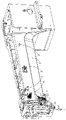
Fig. 1 is the perspective view of the utility model embodiment.
Fig. 2 is the Facad structure sketch map of Fig. 1.
Fig. 3 is the assembling decomposing schematic representation of Fig. 1.
The specific embodiment
Embodiment to the utility model describes in further detail below in conjunction with accompanying drawing.
Fig. 1 is extremely shown in Figure 3 to be the structural representation of the utility model.
Reference numeral wherein is: head 1; Fixing boss platform 1a; Annulus holder 1b; Fixed station 1c; Thread hooking plate 12; Cross line guide post 2; Fixed bar 2a; Conductor rod 2b; Cross line guide plate 3; Side plate 3a; Upper plate 3b; Tension disk 4; Thread tension stud axle 41; Clamp dish 42; Tension regulating thumb nut 43; Clamp spring 44; Loose ends device 5; Clamp pedestal 51; Stopper slot 51a; Thread tension stud 52; Axial notch 52a; The first clamp dish 53; The second clamp dish 54; Clamp platen 55; Bar shaped baffle plate 55a; End cap 56; Drive rod 57; Holddown spring 58; Thread take-up spring 59; Turn 59a; Take-up arm 59b; Shank 6; Lead spring 61; Line cooler 7; Cooling bath 7a; Malthoid 71; Cross line hook 72; Casing hook line bar 8; Hold-down nut 81; Rubber sleeve 82.
As shown in Figure 1; The head string-passing structure of the pattern sewing machine of the utility model; Comprise head 1, be installed with two at the sidewall of head 1 and cross line guide posts 2, cross line guide post 2 and comprise fixed bar 2a that is connected with head 1 sidewall and the conductor rod 2b that is shaped on the line hole.Be fixed with line guide plate 3 between the line guide post 2 excessively at two.Cross line guide plate 3 and be made up of side plate 3a and upper plate 3b, side plate 3a is fixedly connected with head 1 sidewall, and upper plate 3b is shaped on cable-through hole.
On head 1, thread take-up tension lever is installed, is shaped on protruding fixedly boss platform 1a at head 1 sidewall of thread take-up tension lever one side, fixedly boss platform 1a is fixed with tension disk 4.
Tension disk 4 comprise with fixing boss platform 1a on the equipped mutually thread tension stud axle 41 of installing hole; Be arranged with two clamp dishes 42 on the thread tension stud axle 41; Be provided with tension regulating thumb nut 43 in the end of thread tension stud axle 41, between clamp dish 42 and tension regulating thumb nut 43, be provided with the clamp spring 44 that is used to compress two clamp dishes 42.Upper thread is located between two clamp dishes 42, and clamp dish 42 suitably clamps upper thread under the elastic force effect of clamp spring 44.Through rotation tension regulating thumb nut 43, elastic force size that can adjustable clamp wire spring 44.
Loose ends device 5 comprises the clamp pedestal 51 that is arranged on the annulus holder 1b, thread tension stud 52, the centers in the clamp pedestal 51 of being fixedly installed on are provided with manhole and slip cap is located at the first outer clamp dish 53 of thread tension stud 52 and the second clamp dish 54, it is outer and be used to compress the clamp platen 55 of the first clamp dish 53 and the second clamp dish 54 and the end cap 56 that is fixed on thread tension stud 52 ends to be sheathed on thread tension stud 52.
Clamp platen 55 middle parts are shaped on the through hole that matches with thread tension stud 52, are shaped on bar shaped baffle plate 55a at the middle part of through hole.Thread tension stud 52 is shaped on the axial notch 52a that can snap in bar shaped baffle plate 55a along its axle center.Axle center at thread tension stud 52 is shaped on through hole, and in through hole, sliding is provided with drive rod 57, matches with bar shaped baffle plate 55a in the end of drive rod 57.Between clamp platen 55 and end cap 56, be provided with holddown spring 58.
Upper thread is located between the first clamp dish 53 and the second clamp dish 54, and the second clamp dish 54 suitably clamps upper thread under the effect of clamp platen 55 and holddown spring 58.When needing loose ends, drive rod 57 withstands the bar shaped baffle plate 55a of clamp platen 55, and holddown spring 58 is shunk, and discharges the clamping force between the first clamp dish 53 and the second clamp dish 54.
Clamp pedestal 51 is provided with thread take-up spring 59.Thread take-up spring 59 comprises turn 59a and the take-up arm 59b that links to each other with turn 59a one end.Turn 59a is sheathed between thread tension stud 52 and the clamp pedestal 51 and the termination of turn 59a is fixedly connected with thread tension stud 52, and take-up arm 59b is arranged in the stopper slot 51a of clamp pedestal 51.
Drive rod 57 passes annulus holder 1b and matches with driving mechanism, and driving mechanism is provided with the power rail that is used to promote drive rod 57.Driving mechanism can be electromagnetic drive mechanism or pneumatic drive mechanism.Driving mechanism is fixed on the installing plate, and is provided with fixed cap.
The sidewall of head 1 is installed with line cooler 7, and line cooler 7 is shaped on cooling bath 7a, is provided with malthoid 71 in the cooling bath 7a, is provided with line hook 72 in the side of cooling bath 7a.
Opposite side at thread take-up tension lever is fixed with thread hooking plate 12.The thread take-up tension lever below is shaped on fixed station 1c, and fixed station 1c is provided with casing hook line bar 8 through hold-down nut 81, and hold-down nut 81 bags are provided with rubber sleeve 82.Be fixed with lead spring 61 on the shank 6.
The most preferred embodiment of the utility model is illustrated, and various variations of being made by those of ordinary skills or remodeling can not break away from the scope of the utility model.
Claims (10)
1. the head string-passing structure of a pattern sewing machine; Comprise head (1); It is characterized in that: the sidewall at said head (1) is installed with two line guide posts (2) excessively, and the described line guide post (2) of crossing comprises fixed bar (2a) that is connected with head (1) sidewall and the conductor rod (2b) that is shaped on the line hole; Be fixed with line guide plate (3) two said mistakes between the line guide post (2); The described line guide plate (3) of crossing is made up of side plate (3a) and upper plate (3b), and described side plate (3a) is fixedly connected with head (1) sidewall, and described upper plate (3b) is shaped on cable-through hole.
2. the head string-passing structure of a kind of pattern sewing machine according to claim 1; It is characterized in that: described head (1) is equipped with thread take-up tension lever; Head (1) sidewall in said thread take-up tension lever one side is shaped on protruding fixedly boss platform (1a), and described fixedly boss platform (1a) is fixed with tension disk (4).
3. the head string-passing structure of a kind of pattern sewing machine according to claim 2; It is characterized in that: described tension disk (4) comprise with fixing boss platform (1a) on the equipped mutually thread tension stud axle (41) of installing hole; Be arranged with two clamp dishes (42) on the described thread tension stud axle (41); Be provided with tension regulating thumb nut (43) in the end of thread tension stud axle (41), between clamp dish (42) and tension regulating thumb nut (43), be provided with the clamp spring (44) that is used to compress two clamp dishes (42).
4. the head string-passing structure of a kind of pattern sewing machine according to claim 3 is characterized in that: head (1) sidewall of described tension disk (4) below is shaped on annulus holder (1b), and described annulus holder (1b) is fixed with loose ends device (5).
5. the head string-passing structure of a kind of pattern sewing machine according to claim 4; It is characterized in that: described loose ends device (5) comprises the clamp pedestal (51) that is arranged on the annulus holder (1b), thread tension stud (52), the center in the clamp pedestal (51) of being fixedly installed on is provided with manhole and slip cap is located at thread tension stud (52) the outer first clamp dish (53) and the second clamp dish (54), be sheathed on thread tension stud (52) and be used to compress the clamp platen (55) of the first clamp dish (53) and the second clamp dish (54) and the end cap (56) that is fixed on thread tension stud (52) end outward; Described clamp platen (55) middle part is shaped on the through hole that matches with thread tension stud (52), is shaped on bar shaped baffle plate (55a) at the middle part of said through hole; Described thread tension stud (52) is shaped on the axial notch (52a) that can snap in bar shaped baffle plate (55a) along its axle center; Axle center at thread tension stud (52) is shaped on through hole, and in through hole, sliding is provided with drive rod (57), matches with bar shaped baffle plate (55a) in the end of said drive rod (57); Between said clamp platen (55) and end cap (56), be provided with holddown spring (58).
6. the head string-passing structure of a kind of pattern sewing machine according to claim 5, it is characterized in that: described clamp pedestal (51) is provided with thread take-up spring (59); Described thread take-up spring (59) comprises turn (59a) and the take-up arm (59b) that links to each other with turn (59a) end; Described turn (59a) is sheathed between thread tension stud (52) and the clamp pedestal (51) and the termination of turn (59a) is fixedly connected with thread tension stud (52), and described take-up arm (59b) is arranged in the stopper slot (51a) of clamp pedestal (51).
7. the head string-passing structure of a kind of pattern sewing machine according to claim 6, it is characterized in that: said drive rod (57) passes annulus holder (1b) and matches with driving mechanism, and described driving mechanism is provided with the power rail that is used to promote drive rod (57).
8. the head string-passing structure of a kind of pattern sewing machine according to claim 7; It is characterized in that: the sidewall of said head (1) is installed with line cooler (7); Described line cooler (7) is shaped on cooling bath (7a); Be provided with malthoid (71) in the cooling bath (7a), be provided with line hook (72) in a side of cooling bath (7a).
9. the head string-passing structure of a kind of pattern sewing machine according to claim 8, it is characterized in that: the opposite side at thread take-up tension lever is fixed with thread hooking plate (12); Described thread take-up tension lever below is shaped on fixed station (1c), and fixed station (1c) is provided with casing hook line bar (8) through hold-down nut (81), and described hold-down nut (81) bag is provided with rubber sleeve (82).
10. the head string-passing structure of a kind of pattern sewing machine according to claim 9 is characterized in that: be fixed with lead spring (61) on the described shank (6).
Priority Applications (1)
| Application Number | Priority Date | Filing Date | Title |
|---|---|---|---|
| CN 201220062599 CN202492691U (en) | 2012-02-24 | 2012-02-24 | Handpiece thread guide structure of pattern sewing machine |
Applications Claiming Priority (1)
| Application Number | Priority Date | Filing Date | Title |
|---|---|---|---|
| CN 201220062599 CN202492691U (en) | 2012-02-24 | 2012-02-24 | Handpiece thread guide structure of pattern sewing machine |
Publications (1)
| Publication Number | Publication Date |
|---|---|
| CN202492691U true CN202492691U (en) | 2012-10-17 |
Family
ID=46998926
Family Applications (1)
| Application Number | Title | Priority Date | Filing Date |
|---|---|---|---|
| CN 201220062599 Expired - Fee Related CN202492691U (en) | 2012-02-24 | 2012-02-24 | Handpiece thread guide structure of pattern sewing machine |
Country Status (1)
| Country | Link |
|---|---|
| CN (1) | CN202492691U (en) |
Cited By (1)
| Publication number | Priority date | Publication date | Assignee | Title |
|---|---|---|---|---|
| CN112048843A (en) * | 2020-09-15 | 2020-12-08 | 西安标准工业股份有限公司 | A kind of intelligent upper thread tension adjustment device and adjustment method thereof |
-
2012
- 2012-02-24 CN CN 201220062599 patent/CN202492691U/en not_active Expired - Fee Related
Cited By (1)
| Publication number | Priority date | Publication date | Assignee | Title |
|---|---|---|---|---|
| CN112048843A (en) * | 2020-09-15 | 2020-12-08 | 西安标准工业股份有限公司 | A kind of intelligent upper thread tension adjustment device and adjustment method thereof |
Similar Documents
| Publication | Publication Date | Title |
|---|---|---|
| CN203679463U (en) | A machine head of a wire-cutting machine tool provided with a threading device | |
| CN203697739U (en) | File punching, threading bookbinding integrated machine | |
| CN202492691U (en) | Handpiece thread guide structure of pattern sewing machine | |
| CN202658411U (en) | Chain ribbon embroidery mechanism | |
| CN203593875U (en) | Mechanism for assisting in needle threading | |
| CN201952625U (en) | Thread-pressing device for embroidery machine | |
| CN201501982U (en) | Three-dimensional embroidery mechanism | |
| CN202671846U (en) | Threading structure of double-needle loop sewing machine | |
| TWI355436B (en) | ||
| CN204980598U (en) | Twisting frame after improvement | |
| CN204999398U (en) | Doubling device | |
| CN210286262U (en) | Winding device for textile production | |
| CN204023154U (en) | The four eyed button of being located on button attaching machine is made coiling auxiliary device | |
| CN202626388U (en) | Cradle device of rotor spinning machine | |
| CN204325725U (en) | A kind of line mechanism excessively for stitching in embroidery machine | |
| CN203411785U (en) | Handpiece structure of towel embroidery with taping embroidery | |
| CN204434916U (en) | With the Sewing machines of tension device | |
| CN204097702U (en) | A kind of auxiliary presser foot of Sewing machines | |
| CN204097703U (en) | A kind of auxiliary presser foot | |
| CN201050009Y (en) | Middle threading device for computer embroidery machine | |
| CN202317469U (en) | Solder wire passing, pressing and pulling system | |
| CN202347267U (en) | Upper cover structure of eyelet buttonhole sewing machine | |
| CN203562890U (en) | Clamp assembly of chain-type stator winding machine | |
| CN203393428U (en) | Thread guide frame of multi-needle-head sewing machine | |
| CN203440649U (en) | Thread crimping device on a computerized embroidery machine |
Legal Events
| Date | Code | Title | Description |
|---|---|---|---|
| C14 | Grant of patent or utility model | ||
| GR01 | Patent grant | ||
| C41 | Transfer of patent application or patent right or utility model | ||
| TR01 | Transfer of patent right |
Effective date of registration: 20161012 Address after: 315100 Zhejiang city of Ningbo province Yinzhou District Jingu Road No. 219 Patentee after: NINGBO SUPREME ELECTRONIC MACHINERY CO., LTD. Address before: 315100 No. 528 Jin Yuan Road, Yinzhou investment center, Ningbo, Zhejiang, Yinzhou District Patentee before: Ningbo Supreme Electronic Technology Co., Ltd. |
|
| CF01 | Termination of patent right due to non-payment of annual fee |
Granted publication date: 20121017 Termination date: 20200224 |
|
| CF01 | Termination of patent right due to non-payment of annual fee |