CN202492440U - Sludge stirring tank - Google Patents

Sludge stirring tank Download PDF

Info

Publication number
CN202492440U
CN202492440U CN2012200646937U CN201220064693U CN202492440U CN 202492440 U CN202492440 U CN 202492440U CN 2012200646937 U CN2012200646937 U CN 2012200646937U CN 201220064693 U CN201220064693 U CN 201220064693U CN 202492440 U CN202492440 U CN 202492440U
Authority
CN
China
Prior art keywords
sludge
tank
stirring
tank body
mud
Prior art date
Legal status (The legal status is an assumption and is not a legal conclusion. Google has not performed a legal analysis and makes no representation as to the accuracy of the status listed.)
Expired - Fee Related
Application number
CN2012200646937U
Other languages
Chinese (zh)
Inventor
何坚
马勇
匡鸿
郑正
陆民宪
Current Assignee (The listed assignees may be inaccurate. Google has not performed a legal analysis and makes no representation or warranty as to the accuracy of the list.)
Cement Co Ltd Of Shanghai Building Material Group
Fudan University
Original Assignee
Cement Co Ltd Of Shanghai Building Material Group
Fudan University
Priority date (The priority date is an assumption and is not a legal conclusion. Google has not performed a legal analysis and makes no representation as to the accuracy of the date listed.)
Filing date
Publication date
Application filed by Cement Co Ltd Of Shanghai Building Material Group, Fudan University filed Critical Cement Co Ltd Of Shanghai Building Material Group
Priority to CN2012200646937U priority Critical patent/CN202492440U/en
Application granted granted Critical
Publication of CN202492440U publication Critical patent/CN202492440U/en
Anticipated expiration legal-status Critical
Expired - Fee Related legal-status Critical Current

Links

Images

Landscapes

  • Mixers Of The Rotary Stirring Type (AREA)

Abstract

本实用新型属于环保技术领域,具体为一种污泥搅拌罐。该污泥搅拌罐主要包括罐体,罐体上部设有的减速电机,在减速电机的轴上连接的搅拌轴,所述的搅拌轴插入罐体内部。在罐体的边壁上,设有加强肋板,加强肋板上设有可通过流体的孔洞;在加强肋板旁边,设有通气管,通气管直接联通至搅拌罐体的下部。在罐体底部,设有排空管。本实用新型具有以下优点:搅拌桨叶在搅拌的过程中,带动污泥流体与周边的加强肋板撞击,在边壁区域形成较强的紊流,避免了污泥物料对边壁的粘附和结团;在加强肋板边设有通气管,在搅拌的过程中,可通过通气管向搅拌罐内通入空气,强化搅拌罐内的紊流,促进污泥稀释的均质化。本装置对污泥的稀释搅拌具有优异的效果。

Figure 201220064693

The utility model belongs to the technical field of environmental protection, in particular to a sludge stirring tank. The sludge mixing tank mainly includes a tank body, a decelerating motor arranged on the upper part of the tank body, and a stirring shaft connected to the shaft of the decelerating motor, and the agitating shaft is inserted into the inside of the tank body. On the side wall of the tank body, there are reinforcing ribs, and holes through which fluid can pass are arranged on the reinforcing ribs; beside the reinforcing ribs, there is a ventilation pipe, which is directly connected to the lower part of the stirring tank. At the bottom of the tank, there is an emptying pipe. The utility model has the following advantages: during the stirring process, the stirring blades drive the sludge fluid to collide with the surrounding reinforcing ribs, forming strong turbulent flow in the side wall area, and avoiding the adhesion of the sludge material to the side wall and agglomeration; there is a ventilation pipe on the side of the reinforcement rib, and during the stirring process, air can be introduced into the mixing tank through the ventilation pipe to strengthen the turbulent flow in the mixing tank and promote the homogenization of sludge dilution. The device has an excellent effect on the dilution and stirring of sludge.

Figure 201220064693

Description

Sludge agitator tank
Technical field
The utility model belongs to environmental technology field, is specifically related to a kind of device of mud thin up.
Background technology
By the end of the year 2011, nearly 3000 urban wastewater treatment firms have been built up in the whole nation, and a day sewage treatment capacity reaches billion cubic meter more than 1.0, will produce a large amount of active sludge thus.Mud is the solid precipitation material that is produced by water and sewage treatment process, and pre-treatment, preliminary sedimentation tank, second pond that generally derives from water treatment etc. located.Without the mud of stabilizing treatment, very easily corrupt and produce stench because of organic content is high, especially contain a large amount of germs, parasitic ovum and virus, be prone to cause the secondary pollutions such as propagation of transmissible disease.The thickening device (comprising belt machine and whizzer) of mud generally is concentrated into water ratio about 80% with mud and transports outward processing again in the sewage work at present.
National house in 2009 and town and country construction portion, Environmental Protection Department, the Ministry of Science and Technology unite and have issued " the urban wastewater treatment firm sludge treatment is disposed and pollution prevention technique policy (trying) " new policy; With farmland utilization clear and definite requirement is arranged to the mud of municipal wastewater treatment plant is stable, require the water ratio of mud to be reduced to below 60% and just can advance the landfill yard landfill.Since usually municipal sludge at water ratio behind the mechanical dehydration generally more than 80%; Further deep dehydration is handled if desired; Can adopt water ratio in the concentration basin is 97% the direct deep dehydration of mud; After perhaps water ratio being the dilution of 80% mud, stir fully reaction, and then adopt device for dehydrating sladge waste such as diaphragm type plate-and-frame filter press further the water ratio of mud to be reduced to below 60% with the deep dehydration medicament.Thereby, for the mud that part needs dilution, need reasonably design the dilution stirred pot of mud.
Mud is flocculating through adding polymeric flocculant after concentrating through sewage work, the belt filter press or the whizzer centrifuge dehydration that get into sewage work again, and the mud after existing belt filter press of process or the whizzer centrifuge dehydration is because biological cells in sludge and colloidal content are bigger; Be the mucilage shape, water molecules is by one deck colloid parcel, for this reason; The design of general stirred pot; Be difficult to mud is stirred at short notice, mud is generally stirring tank body periphery deposition or is adhering to, and it is even that mud is difficult to thin up; If strengthen the Dilution ratio of mud, then there is the long or bigger problem of design power of agitator of follow-up deep dehydration cycle.
Domestic number of patent application is the device that 200820232274.3 patent provides a kind of slurry stirred pot; This device has effect preferably for the little particle of particle viscosity; But for the bigger material of this viscosity of mud; Wall has viscous effect on the stirred pot limit, thereby still exists stirring to be difficult to uniform problem.
Summary of the invention
The purpose of the utility model is to provide a kind of mixing effect good, mixes full and uniform mud dilution whipping appts.
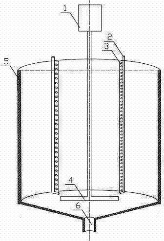
The mud whipping appts that the utility model provides, its structure is as shown in Figure 1, comprises tank body 5, reducing motor 1 and stir shaft 4; Said reducing motor 1 is located at tank body 5 tops, on the axle of reducing motor 1, connects described stir shaft 4; Stir shaft 4 inserts tank body 5 inside; On the wall of the limit of tank body 5, be provided with deep floor 3, deep floor 3 is provided with and can passes through the fluidic hole; On deep floor 3 next doors, be provided with ventpipe 2, ventpipe 2 direct UNICOMs are to the bottom of stirring tank body; In tank base, be provided with evacuated tube 6.
The special character of this sludge agitator tank is:
1) on the limit wall that stirs tank body, be provided with deep floor, floor is provided with and can passes through the fluidic hole;
2) the strengthening rib edges of boards are provided with ventpipe, can pass through ventpipe bubbling air in stirred pot.
The utility model compared with prior art has the following advantages:
1, because stir shaft is provided with agitating vane, agitating vane drive mud fluid and peripheral deep floor bump, thereby the wall zone forms stronger turbulent flow on the limit, has avoided the adhesion and the conglomeration of mud material opposite side wall in the process that stirs;
2, be provided with ventpipe at the strengthening rib edges of boards,, need to adopt air because in the deeply dehydrating sludge process.Thereby in the process that stirs, can pass through ventpipe bubbling air in stirred pot, and strengthen the turbulent flow in the stirred pot, promote homogenizing of mud dilution.
Description of drawings
Fig. 1 is the structural representation of the utility model.
Label among the figure: the 1st, reducing motor, the 2nd, ventpipe, the 3rd, deep floor, the 4th, stir shaft, the 5th, tank body, the 6th, evacuated tube.
Embodiment
As shown in the figure, a kind of sludge agitator tank comprises tank body 5, and tank body 5 tops are provided with reducing motor 1, on the axle of reducing motor 1, is connected with stir shaft 4, and described stir shaft 4 inserts tank body 5 inside.On the wall of the limit of tank body 5, be provided with deep floor 3, deep floor 3 is provided with and can passes through the fluidic hole; On deep floor 3 next doors, be provided with ventpipe 2, ventpipe 2 direct UNICOMs are to the bottom of stirring tank body.In tank base, be provided with evacuated tube 6.
In stirred pot 5, add earlier the water of sludge quantity 120% (quality) earlier, start agitator motor 1, the water ratio that needs are stirred is that 80% mud adds in the stirred pot 5.Because on the wall of the limit of tank body 5, be provided with deep floor 3, deep floor 3 is provided with and can passes through the fluidic hole; After starting reducing motor 1, stir shaft 4 begins to stir mud, and mud fluid and deep floor 3 clash into and produce turbulent flow, wash away the limit wall of stirred pot 5, make that wall can't deposit mud on the limit.When stirring, bubbling air in ventpipe 2, because ventpipe 2 direct UNICOMs are to the bottom of stirring tank body, air is gone out from the bottom of stirred pot, has strengthened the interior turbulent flow of stirred pot, thereby has promoted homogenizing of mud.Big solid particulate in the sludge tank, the middle part that concentrates on stirred pot is through the evacuated tube emptying.

Claims (1)

1. a sludge agitator tank is characterized in that: comprise tank body, reducing motor and stir shaft; Said reducing motor is located at tank body top, on the axle of reducing motor, connects described stir shaft; Stir shaft inserts tank interior; On the wall of the limit of tank body, be provided with deep floor, deep floor is provided with and can passes through the fluidic hole; On the deep floor next door, be provided with ventpipe, the direct UNICOM of ventpipe is to the bottom of stirring tank body; In tank base, be provided with evacuated tube.
CN2012200646937U 2012-02-27 2012-02-27 Sludge stirring tank Expired - Fee Related CN202492440U (en)

Priority Applications (1)

Application Number Priority Date Filing Date Title
CN2012200646937U CN202492440U (en) 2012-02-27 2012-02-27 Sludge stirring tank

Applications Claiming Priority (1)

Application Number Priority Date Filing Date Title
CN2012200646937U CN202492440U (en) 2012-02-27 2012-02-27 Sludge stirring tank

Publications (1)

Publication Number Publication Date
CN202492440U true CN202492440U (en) 2012-10-17

Family

ID=46998676

Family Applications (1)

Application Number Title Priority Date Filing Date
CN2012200646937U Expired - Fee Related CN202492440U (en) 2012-02-27 2012-02-27 Sludge stirring tank

Country Status (1)

Country Link
CN (1) CN202492440U (en)

Cited By (3)

* Cited by examiner, † Cited by third party
Publication number Priority date Publication date Assignee Title
CN103936242A (en) * 2014-04-03 2014-07-23 西安交通大学 Sludge homogenization and viscosity reduction device
WO2018032814A1 (en) * 2016-08-16 2018-02-22 中电建水环境治理技术有限公司 Multi-functional sludge conditioning pool for treating and mechanical dewatering of polluted river and lake mouth sediment
CN109329955A (en) * 2018-10-15 2019-02-15 南安市起胤机械科技有限公司 A rapid beating device for preventing fruit fiber from entanglement

Cited By (5)

* Cited by examiner, † Cited by third party
Publication number Priority date Publication date Assignee Title
CN103936242A (en) * 2014-04-03 2014-07-23 西安交通大学 Sludge homogenization and viscosity reduction device
CN103936242B (en) * 2014-04-03 2015-12-30 西安交通大学 A kind of mud homogeneous viscosity-falling unit
WO2018032814A1 (en) * 2016-08-16 2018-02-22 中电建水环境治理技术有限公司 Multi-functional sludge conditioning pool for treating and mechanical dewatering of polluted river and lake mouth sediment
CN109329955A (en) * 2018-10-15 2019-02-15 南安市起胤机械科技有限公司 A rapid beating device for preventing fruit fiber from entanglement
CN109329955B (en) * 2018-10-15 2020-12-04 浙江启博知识产权运营有限公司 A rapid beating device for preventing fruit fiber from entanglement

Similar Documents

Publication Publication Date Title
CN102153267A (en) Method for modifying and dewatering sludge
CN211170019U (en) Sedimentation tank for sewage treatment
CN220976630U (en) Intelligent high-efficient dephosphorization equipment
CN205294959U (en) Uasb reactor
CN211936520U (en) Stirrer device for dissolving organic polymer cation emulsion
CN203295250U (en) Novel high-speed high-efficiency sedimentation tank for sand addition
CN102441297B (en) Sludge reflux flocculation sedimentation tank
CN104743743A (en) Upward flowing type deposition-hydrolyzing and two-stage AO biochemical treatment system and application thereof
KR101769988B1 (en) Anaerobic digester of solid and liquid organic waste
CN203845883U (en) Textile wastewater coagulation inclined pipe combined settling pond
CN101343100A (en) Duplex treatment device for building construction wastewater
CN201470160U (en) Mechanical stirring clarifier
CN201713389U (en) Pre-treatment system for thermal seawater desalination
CN202263433U (en) Sludge backflow flocculation and sedimentation tank
CN205420078U (en) Printing and dyeing wastewater advanced treatment unit is concentrated to industry park
CN218951111U (en) Magnetic coagulation sedimentation integrated fecal water treatment device
CN207581517U (en) A kind of industrial wastewater settler
CN207525129U (en) A kind of efficient dosing system of flocculant
CN206454508U (en) A kind of polyacrylamide dissolver
CN207903965U (en) A kind of novel flocculation equipment
CN211536650U (en) High-efficiency flocculation mud scraper
CN210559782U (en) Suspension medium layer filtering system based on mechanical stirring layering
CN212151731U (en) Novel upflow coagulation and flocculation device
CN202729865U (en) Sludge recirculation reactor for treating industrial organic wastewater
CN210287100U (en) Septic tank filth sclerosis processor

Legal Events

Date Code Title Description
C14 Grant of patent or utility model
GR01 Patent grant
CF01 Termination of patent right due to non-payment of annual fee

Granted publication date: 20121017

Termination date: 20150227

EXPY Termination of patent right or utility model