CN202492233U - Branch wire pressing structure - Google Patents
Branch wire pressing structure Download PDFInfo
- Publication number
- CN202492233U CN202492233U CN2012200727794U CN201220072779U CN202492233U CN 202492233 U CN202492233 U CN 202492233U CN 2012200727794 U CN2012200727794 U CN 2012200727794U CN 201220072779 U CN201220072779 U CN 201220072779U CN 202492233 U CN202492233 U CN 202492233U
- Authority
- CN
- China
- Prior art keywords
- hinged
- cylinder
- square frame
- sliding seat
- pressure roller
- Prior art date
- Legal status (The legal status is an assumption and is not a legal conclusion. Google has not performed a legal analysis and makes no representation as to the accuracy of the status listed.)
- Expired - Fee Related
Links
Images

Classifications
-
- Y—GENERAL TAGGING OF NEW TECHNOLOGICAL DEVELOPMENTS; GENERAL TAGGING OF CROSS-SECTIONAL TECHNOLOGIES SPANNING OVER SEVERAL SECTIONS OF THE IPC; TECHNICAL SUBJECTS COVERED BY FORMER USPC CROSS-REFERENCE ART COLLECTIONS [XRACs] AND DIGESTS
- Y02—TECHNOLOGIES OR APPLICATIONS FOR MITIGATION OR ADAPTATION AGAINST CLIMATE CHANGE
- Y02W—CLIMATE CHANGE MITIGATION TECHNOLOGIES RELATED TO WASTEWATER TREATMENT OR WASTE MANAGEMENT
- Y02W30/00—Technologies for solid waste management
- Y02W30/50—Reuse, recycling or recovery technologies
- Y02W30/82—Recycling of waste of electrical or electronic equipment [WEEE]
Landscapes
- Coils Of Transformers For General Uses (AREA)
Abstract
本实用新型公开了一种分线压紧结构,包括转动安装的分线盘,分线盘环壁的外侧安装有底座,底座上安装有滑座,滑座一侧铰接有气缸,气缸对侧的滑座上铰接有方形框,方形框的中部转动安装有转轴,转轴与所述的气缸的活塞杆端部铰接,方形框端部转动安装有压辊,压辊上开有多道环形凹槽,环形凹槽与分线盘上的绕线槽正对。本实用新型结构设计合理,通过气缸推动方形框使得压辊与分线盘的绕线槽正对,绕线过程中,分线盘上经过的线芯不会脱出绕线槽,提高了绕线的质量和效率。
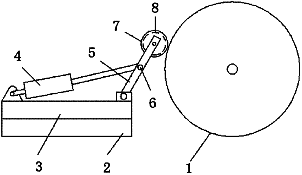
The utility model discloses a thread-distributing pressing structure, which comprises a thread-distributing disc installed in rotation, a base is installed on the outer side of the ring wall of the line-distributing disc, a sliding seat is installed on the base, a cylinder is hinged on one side of the sliding seat, and a A square frame is hinged on the sliding seat, and a rotating shaft is installed in the middle of the square frame. The rotating shaft is hinged with the end of the piston rod of the cylinder, and a pressure roller is installed on the end of the square frame. Groove, the annular groove is opposite to the winding groove on the distribution disc. The utility model has a reasonable structural design, and the cylinder pushes the square frame so that the pressure roller and the wire winding groove of the wire splitting reel are facing each other. quality and efficiency.
Description
Claims (2)
Priority Applications (1)
| Application Number | Priority Date | Filing Date | Title |
|---|---|---|---|
| CN2012200727794U CN202492233U (en) | 2012-03-01 | 2012-03-01 | Branch wire pressing structure |
Applications Claiming Priority (1)
| Application Number | Priority Date | Filing Date | Title |
|---|---|---|---|
| CN2012200727794U CN202492233U (en) | 2012-03-01 | 2012-03-01 | Branch wire pressing structure |
Publications (1)
| Publication Number | Publication Date |
|---|---|
| CN202492233U true CN202492233U (en) | 2012-10-17 |
Family
ID=46998469
Family Applications (1)
| Application Number | Title | Priority Date | Filing Date |
|---|---|---|---|
| CN2012200727794U Expired - Fee Related CN202492233U (en) | 2012-03-01 | 2012-03-01 | Branch wire pressing structure |
Country Status (1)
| Country | Link |
|---|---|
| CN (1) | CN202492233U (en) |
Cited By (7)
| Publication number | Priority date | Publication date | Assignee | Title |
|---|---|---|---|---|
| CN103950785A (en) * | 2014-04-23 | 2014-07-30 | 山西太钢不锈钢股份有限公司 | Control device for preventing spool equipment cable falling |
| CN104377030A (en) * | 2014-12-11 | 2015-02-25 | 天津鑫坤泰预应力专业技术有限公司 | Steel strand pay-off reel with coil pressing devices |
| CN106314852A (en) * | 2015-06-26 | 2017-01-11 | 广东联塑机器制造有限公司 | Pipe compression positioning device for automatic winder |
| CN108010715A (en) * | 2016-10-28 | 2018-05-08 | 上海置信电气非晶有限公司 | A kind of coil is tightly around device |
| CN108455370A (en) * | 2018-03-20 | 2018-08-28 | 宗立武 | One kind compressing rolling type communication cable wrap-up |
| CN111634750A (en) * | 2020-06-03 | 2020-09-08 | 山西东辉新能源汽车研究院有限公司 | Winding device |
| CN111908249A (en) * | 2020-08-10 | 2020-11-10 | 福建康百赛新材料有限公司 | Automatic winding and efficient bundling integrated equipment for light elastic ES fibers |
-
2012
- 2012-03-01 CN CN2012200727794U patent/CN202492233U/en not_active Expired - Fee Related
Cited By (7)
| Publication number | Priority date | Publication date | Assignee | Title |
|---|---|---|---|---|
| CN103950785A (en) * | 2014-04-23 | 2014-07-30 | 山西太钢不锈钢股份有限公司 | Control device for preventing spool equipment cable falling |
| CN104377030A (en) * | 2014-12-11 | 2015-02-25 | 天津鑫坤泰预应力专业技术有限公司 | Steel strand pay-off reel with coil pressing devices |
| CN106314852A (en) * | 2015-06-26 | 2017-01-11 | 广东联塑机器制造有限公司 | Pipe compression positioning device for automatic winder |
| CN108010715A (en) * | 2016-10-28 | 2018-05-08 | 上海置信电气非晶有限公司 | A kind of coil is tightly around device |
| CN108455370A (en) * | 2018-03-20 | 2018-08-28 | 宗立武 | One kind compressing rolling type communication cable wrap-up |
| CN111634750A (en) * | 2020-06-03 | 2020-09-08 | 山西东辉新能源汽车研究院有限公司 | Winding device |
| CN111908249A (en) * | 2020-08-10 | 2020-11-10 | 福建康百赛新材料有限公司 | Automatic winding and efficient bundling integrated equipment for light elastic ES fibers |
Similar Documents
| Publication | Publication Date | Title |
|---|---|---|
| CN202492233U (en) | Branch wire pressing structure | |
| CN202897674U (en) | Reel | |
| CN104477698A (en) | Mechanical damping type passive pay-off device | |
| CN206312613U (en) | Optical fiber composite-type flexible drum cable | |
| CN203922284U (en) | A kind of cable pressing device | |
| CN203179616U (en) | Rapid coiling apparatus | |
| CN202205517U (en) | Cable wire twisting machine | |
| CN102897602A (en) | Reel | |
| CN202068126U (en) | Assembled table roll | |
| CN205527034U (en) | Cable conductor coiler | |
| CN202905285U (en) | A doubling winder | |
| CN204079074U (en) | A kind of vertical dibit take-up reel | |
| CN204916610U (en) | Novel data line strapping | |
| CN104218745A (en) | Winding method of multi-thread planar winding | |
| CN204680482U (en) | Multiply core automatic winding device | |
| CN203223805U (en) | Floor lamp with reel | |
| CN202134281U (en) | Cable creaser wheel | |
| CN203512947U (en) | Winding device | |
| CN202126886U (en) | Take-up spool convenient in wire withdrawing | |
| CN202558527U (en) | Windlass | |
| CN203225426U (en) | Audio and video signal line with winder | |
| CN201584229U (en) | Steel belt armouring machine | |
| CN202584942U (en) | Electric wire twisting device | |
| CN202816493U (en) | Three-combined lead clamp | |
| CN205114723U (en) | Multipurpose coiling machine |
Legal Events
| Date | Code | Title | Description |
|---|---|---|---|
| C14 | Grant of patent or utility model | ||
| GR01 | Patent grant | ||
| PE01 | Entry into force of the registration of the contract for pledge of patent right |
Denomination of utility model: Branch wire pressing structure Effective date of registration: 20190807 Granted publication date: 20121017 Pledgee: Tianchang vibration financing Company limited by guarantee Pledgor: Anhui Cable Co., Ltd. Registration number: Y2019340000002 |
|
| PE01 | Entry into force of the registration of the contract for pledge of patent right | ||
| PC01 | Cancellation of the registration of the contract for pledge of patent right |
Date of cancellation: 20200731 Granted publication date: 20121017 Pledgee: Tianchang vibration financing Company limited by guarantee Pledgor: ANHUI CABLE Co.,Ltd. Registration number: Y2019340000002 |
|
| PC01 | Cancellation of the registration of the contract for pledge of patent right | ||
| CF01 | Termination of patent right due to non-payment of annual fee |
Granted publication date: 20121017 Termination date: 20200301 |
|
| CF01 | Termination of patent right due to non-payment of annual fee |