CN202492229U - Simple manual winder - Google Patents
Simple manual winder Download PDFInfo
- Publication number
- CN202492229U CN202492229U CN2011205075769U CN201120507576U CN202492229U CN 202492229 U CN202492229 U CN 202492229U CN 2011205075769 U CN2011205075769 U CN 2011205075769U CN 201120507576 U CN201120507576 U CN 201120507576U CN 202492229 U CN202492229 U CN 202492229U
- Authority
- CN
- China
- Prior art keywords
- handle
- gear
- manual simplified
- winder according
- drive link
- Prior art date
- Legal status (The legal status is an assumption and is not a legal conclusion. Google has not performed a legal analysis and makes no representation as to the accuracy of the status listed.)
- Expired - Fee Related
Links
- 230000005540 biological transmission Effects 0.000 claims abstract description 18
- 239000004033 plastic Substances 0.000 claims abstract description 17
- 239000000463 material Substances 0.000 claims abstract description 4
- 239000011241 protective layer Substances 0.000 claims description 6
- 230000000295 complement effect Effects 0.000 claims description 3
- 238000003466 welding Methods 0.000 abstract description 12
- RYGMFSIKBFXOCR-UHFFFAOYSA-N Copper Chemical compound [Cu] RYGMFSIKBFXOCR-UHFFFAOYSA-N 0.000 abstract description 11
- 229910052802 copper Inorganic materials 0.000 abstract 1
- 239000010949 copper Substances 0.000 abstract 1
- 238000005096 rolling process Methods 0.000 abstract 1
- 238000004804 winding Methods 0.000 abstract 1
- 238000004519 manufacturing process Methods 0.000 description 4
- 238000000034 method Methods 0.000 description 4
- 230000000881 depressing effect Effects 0.000 description 3
- 238000012423 maintenance Methods 0.000 description 2
- 230000004048 modification Effects 0.000 description 2
- 238000012986 modification Methods 0.000 description 2
- 230000009286 beneficial effect Effects 0.000 description 1
- 230000007812 deficiency Effects 0.000 description 1
- 239000012467 final product Substances 0.000 description 1
- 244000144992 flock Species 0.000 description 1
- 230000008520 organization Effects 0.000 description 1
Images

Landscapes
- Unwinding Of Filamentary Materials (AREA)
Abstract
Simple and easy manual winder relates to one kind and can realize the instrument of direct welding after the line winding, including the press fastener, transmission module, power module triplex, it is fixed to have a shell, and the shell adopts organic plastic material, and when pushing down the handle, along with the rotation of screw thread above the handle, the transfer line also can take place thereupon with the gear that links to each other with it, connects like this at the press fastener of rearmost also can take place thereupon and rotate, and the rotational speed can be controlled by the operator by oneself, also can decide according to the nature of the copper wire of will rolling up. Therefore, the disordered copper wires pressed in the wire pressing clamp can be gathered together along with rotation to form a concentrated cable which can be directly used for welding.
Description
Technical field
The utility model belongs to mechanical designing technique and welding accessory equipment field, relates to a kind of manual spiral appearance, particularly a kind of directly instrument of welding of can realizing behind the spiral.
Background technology
No matter be in the past or now, the welding process of device welding and cable all can be arranged in commercial production and maintenance of equipment place.The welding cable generally can obtain handling in advance in the middle of some bigger commercial production; Can directly weld then; But in the middle of some small-scale production, if make by hand and the situation such as maintenance of equipment of small number under, Application of Large equipment has a lot of inconvenience.For the less enterprise of some scales, before not realizing mass production, also can often use manual spiral and be used for welding.Therefore, be necessary to study a kind of hand that can replace and come spiral, handle the instrument of scattered copper wire, can improve the efficient of work, convenient welding.
Summary of the invention
To the deficiency that exists in the difference of application and the background technology, the utility model has designed a kind of easy copper wire coil of wire line apparatus.
The technical scheme that the utility model adopted is that manual simplified winder comprises line ball folder, transmission module, three parts of power plant module, has a shell to fix, shell employing organic plastic material.
Described line ball folder is made up of two organic plastic plates that are parallel to each other, long 5cm, and wide is 3cm, and thickness is 3mm, and a side of plastic flagstone is provided with threaded long handle.
The contact surface of said plastic flagstone all scribbles protective layer, and protective layer is one deck TR thin rubber, can effectively prevent the slip of copper wire line, can rotate with long handle after two plastic flagstones combine.
Described long handle is the power resources that the line ball folder rotates.
Described transmission module is made up of transmission gear and drive link, and the transmission gear diameter is 5cm, and drive link is long to be 8cm, and transmission gear directly links to each other with drive link with long handle, drives the rotation of line ball folder.Drive link is connected with the gear of handle part, can transmit the power that handle brings.
Described power plant module is made up of handle and gear, and the diameter of gear is 5cm, can receive the direct driving force of handle.Be designed with screw thread on the handle, be complementary with the tooth pitch of gear, when depressing handle, gear can rotate along with the rotation of screw thread on the handle.
The beneficial effect of the utility model is, and is convenient and swift, can accomplish the spiral process of spuious copper wire line at short notice; Make follow-up welding job more convenient, saved workman's operating time, cost is low; Project organization is comparatively simple, can satisfy popular demand.
Description of drawings
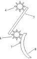
Accompanying drawing 1 is the structural representation of line ball clamping piece in the manual simplified winder of the utility model.
Accompanying drawing 2 is transmission module and a power plant module constructional drawing in the manual simplified winder of the utility model.
Wherein, 1, plastic flagstone; 2, long handle; 3, screw thread; 4, transmission gear; 5, drive link; 6, gear; 7, the strong point; 8, handle.
The specific embodiment
Below accompanying drawings is come the in detail openly specific embodiment of the utility model.
Manual simplified winder comprises line ball folder, transmission module, three parts of power plant module, and the outside has a shell to fix, and shell adopts organic plastic material.
Shown in accompanying drawing 1, described line ball folder is made up of two organic plastic plates that are parallel to each other 1, long 5cm, and wide is 3cm, and thickness is 3mm, and a side of plastic flagstone 1 is provided with threaded 3 long handle 2.
The contact surface of said plastic flagstone 1 all scribbles protective layer, and protective layer is one deck TR thin rubber, can effectively prevent the slip of copper wire line, can rotate with long handle after two plastic flagstones 1 combine.
Described long handle 2 is power resources that the line ball folder rotates.
Shown in accompanying drawing 2, described transmission module is made up of transmission gear 4 and drive link 5, and transmission gear 4 diameters are 5cm, and drive link 5 length are 8cm, and transmission gear 4 directly links to each other with drive link 5 with long handle 2, drives the rotation of line ball folder.Drive link 5 is connected with the gear 6 at handle 8 positions, can transmit the power that handle 8 brings.
Described power plant module is made up of handle 8 and gear 6, and the diameter of gear is 5cm, can receive the direct driving force of handle 8.Be designed with screw thread 3 on the handle 8, be complementary with the tooth pitch of gear 6, when depressing handle 8, gear 6 can rotate along with the rotation of screw thread on the handle 3.
Practical implementation is operating as: the copper wire line of the roll coil of strip at first is added to middle plastic flagstone 1 place as shown in Figure 1 of line ball folder; And fix, when depressing handle 8, along with the rotation of screw thread above the handle 3; Drive link 5 also can rotate with coupled gear thereupon; The line ball folder that is connected extreme end so also can rotate thereupon, and rotating speed can be controlled by the operator voluntarily, also can according to the character of the copper wire that will roll decide.Like this, being pressed in the mixed and disorderly copper wire line of line ball underedge face will flock together along with rotation, forms a branch of concentrated cable, can directly be used for welding.
Accompanying drawing 1 and accompanying drawing 2 have provided the inner structure of winder; Only need add a fixed housing in use and get final product, what this device was finally realized is exactly the motion by operator's hand, drives driving system really; Make the line ball folder begin to rotate; Always line ball is pressed from both sides in-to-in copper wire line and all be rolled into a branch of, conveniently follow-up welding job, process convenient is quick.
The above; Only being the utility model preferred embodiment, is not that the utility model is done any pro forma restriction, and all technical spirit according to the utility model are to any simple modification that above embodiment did; Equivalent variations and modification still belong in the scope of the utility model technical scheme.
Claims (7)
1. manual simplified winder is characterized in that, it mainly comprises line ball folder, transmission module, three parts of power plant module, has a shell to fix, and shell adopts organic plastic material, and the line ball folder is made up of two organic plastic plates that are parallel to each other; Transmission module is made up of transmission gear and drive link; Power plant module is made up of handle and gear.
2. a kind of manual simplified winder according to claim 1 is characterized in that, the long 5cm of described plastic flagstone, and wide is 3cm, and thickness is 3mm, and a side is provided with threaded long handle; The contact surface of plastic flagstone all scribbles protective layer.
3. a kind of manual simplified winder according to claim 2 is characterized in that described protective layer is one deck rubber.
4. a kind of manual simplified winder according to claim 1 is characterized in that described transmission gear diameter is 5cm, is connected with long handle.
5. a kind of manual simplified winder according to claim 1 is characterized in that, described drive link is long for 8cm, is connected with transmission gear.
6. a kind of manual simplified winder according to claim 1 is characterized in that, is designed with screw thread on the described handle, is connected with gear, is complementary with gears tooth pitch.
7. a kind of manual simplified winder according to claim 1 is characterized in that described gear diameter is 5cm, is connected with drive link.
Priority Applications (1)
| Application Number | Priority Date | Filing Date | Title |
|---|---|---|---|
| CN2011205075769U CN202492229U (en) | 2011-12-08 | 2011-12-08 | Simple manual winder |
Applications Claiming Priority (1)
| Application Number | Priority Date | Filing Date | Title |
|---|---|---|---|
| CN2011205075769U CN202492229U (en) | 2011-12-08 | 2011-12-08 | Simple manual winder |
Publications (1)
| Publication Number | Publication Date |
|---|---|
| CN202492229U true CN202492229U (en) | 2012-10-17 |
Family
ID=46998465
Family Applications (1)
| Application Number | Title | Priority Date | Filing Date |
|---|---|---|---|
| CN2011205075769U Expired - Fee Related CN202492229U (en) | 2011-12-08 | 2011-12-08 | Simple manual winder |
Country Status (1)
| Country | Link |
|---|---|
| CN (1) | CN202492229U (en) |
-
2011
- 2011-12-08 CN CN2011205075769U patent/CN202492229U/en not_active Expired - Fee Related
Similar Documents
| Publication | Publication Date | Title |
|---|---|---|
| CN202729453U (en) | Double-roller device for collecting copper materials | |
| CN102490949B (en) | Toothpaste squeezing device | |
| CN202895300U (en) | Coiled material paper element cutting machine | |
| CN202492229U (en) | Simple manual winder | |
| CN202878745U (en) | Full-automatic crimping device for paper bag making machine | |
| CN202429795U (en) | Rim charge high-speed rolling unit | |
| CN204847548U (en) | Automatic cable tie cutting machine | |
| CN103159078A (en) | Simple manual winder | |
| CN204211989U (en) | A kind of cotton-wadded quilt net fixed-length cutting device | |
| CN102351115A (en) | Straw mat pulling device | |
| WO2012033540A3 (en) | Enhanced power compact bolt cutter | |
| CN201472979U (en) | Gear-driven transmission device | |
| CN203753971U (en) | Transmission mechanism for glass measurement and control equipment | |
| CN213923577U (en) | PE pipeline wind | |
| CN103711851A (en) | Durable belt type general machine speed adjusting device | |
| CN204172565U (en) | A kind of blackboard eraser | |
| CN102847652A (en) | UV adhesive curing and production device | |
| CN203856993U (en) | Roller brush speed change system for road surface cleaning machine | |
| CN206723369U (en) | A kind of circular cone star-wheel driving device | |
| CN202657572U (en) | Novel straw conveying device | |
| CN103274014A (en) | Chainless transmission bicycle transmission gear even wear device | |
| CN203919242U (en) | All-in-one is scalded in the reconditioning of photo frame | |
| CN202087627U (en) | Novel steel band reel material collecting device | |
| CN201998427U (en) | Hand-powered and synchronously-driving plastic tube hot melt butt machine | |
| CN203345567U (en) | Cleaning recovery device |
Legal Events
| Date | Code | Title | Description |
|---|---|---|---|
| C14 | Grant of patent or utility model | ||
| GR01 | Patent grant | ||
| CF01 | Termination of patent right due to non-payment of annual fee |
Granted publication date: 20121017 Termination date: 20141208 |
|
| EXPY | Termination of patent right or utility model |