Summary of the invention
Because there is the problem that the chimeric each other assembly program of multi-disc cardboard is loaded down with trivial details and assembling is difficult in prior art, the utility model proposes a kind of package lining structure, is formed by the en plaque base material folded that launches, and comprising:
Base plate has first surface and second surface, and second surface is back in first surface; One group of first side plate lays respectively at the left and right sides of base plate and in correspondence with each other, first side plate also comprises first outer panel, first epipleural and first interior plate; Second side plate, second side plate is positioned at the front side of base plate, and second side plate also comprises second outer panel, second epipleural and second interior plate;
Wherein, on base plate, cut a baffle plate, baffle plate is turned down to first surface; First side plate is turned down to first surface, and first outer panel and first epipleural turn down to second surface; Second side plate is turned down to first surface, and second outer panel and second epipleural turn down to first surface; By this, baffle plate, first side plate and the turnover of second side plate form the package lining structure around base plate.
Can find out from such scheme; The package lining structure that the utility model provides cuts baffle plate and with baffle plate turnover, again with first side plate, the turnover of second side plate on base plate; Center on base plate by baffle plate, first side plate and the turnover of second side plate, to form the package lining box.
Through above-mentioned technological means, the utility model only need use single flap, can reach the technological effect that need can not form the package lining structure through loaded down with trivial details package program.
The specific embodiment
Below will combine accompanying drawing and embodiment to specify the embodiment of the utility model, and how utilize technological means to solve technical matters to the utility model whereby and the implementation procedure of reaching technological effect can make much of and implement according to this.
The package lining structure of at first introducing the utility model and being proposed, and please with reference to shown in Figure 1, Fig. 1 is the utility model package lining structure first embodiment plane outspread drawing.
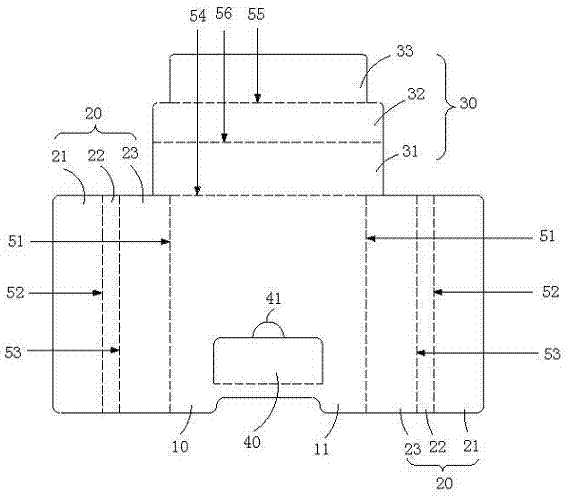
As shown in Figure 1, the package lining structure that the utility model proposed is that the en plaque base material folded by an expansion forms in first embodiment, and the package lining structure comprises: base plate 10, one group of first side plate 20, second side plate 30 and baffle plate 40.Wherein, base plate 10 has first surface 11 and second surface (not illustrating among the figure), and second surface is back in first surface 11; First side plate 20 also comprises first outer panel 21, first epipleural 22 and first interior plate 23; Second side plate 30 also comprises second outer panel 31, second epipleural 32 and second interior plate 33; Dotted line among Fig. 1 is represented fold line; In addition, on base plate 10, cut " ㄇ " shape and cut interruption-forming baffle plate 40.
First side plate 20 lays respectively at the left and right sides of base plate 10 and in correspondence with each other, as shown in Figure 1, in first side plate 20, at first, defining first side plate 20 is first broken line 51 with base plate 10 intersections; Next defines first outer panel 21 and first epipleural, 22 intersections are second broken line 52; And define first epipleural 22 and first interior plate, 23 intersections are tri linear 53.
Second side plate 30 is positioned at the front side of base plate 10, and is as shown in Figure 1, and in second side plate 30, at first, defining second side plate 30 is the 4th broken line 54 with base plate 10 intersections; Next defines second outer panel 31 and second epipleural, 32 intersections are the 5th broken line 55; And define second epipleural 32 and second interior plate, 33 intersections are the 6th broken line 56.
Cut " ㄇ " shape at the lower part of base plate 10 and cut mouth, form baffle plate 40, baffle plate 40 is relative with second side plate, 30 positions.It should be noted that the face shaping that baffle plate 40 cuts can be different shapes such as rectangular shape, trapezoidal shape or semicircular in shape, among the figure with rectangular shape as signal, but do not limit to the utility model with this.The baffle plate of user's pull-up for ease 40 has also cut a semi-circular through hole 41 that makes things convenient for the user to point to stretch into along baffle plate 40 on base plate 10.
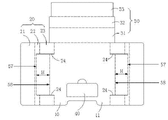
The turnover process of first side plate 20 and second side plate 30 below will be described.At first; Please be simultaneously with reference to figure 1 and shown in Figure 2; According to first surface 11 turnovers of first broken line 51 to base plate 10, the angle of turnover is an an angle of 90 degrees with first side plate 20, first outer panel 21 and first epipleural 22 is turned down to the second surface of base plate 10 according to second broken line 52 and tri linear 53 respectively again; The angle of turnover is an angle of 90 degrees, promptly can first side plate 20 be folded into " ㄇ " shape shape.Then; Again second side plate 30 is turned down according to the first surface 11 of the 4th broken line 54 to base plate 10; The angle of turnover is an an angle of 90 degrees; Second outer panel 31 and second epipleural 32 are turned down to the first surface 11 of base plate 10 according to the 5th broken line 55 and the 6th broken line 56 respectively, the angle of turnover is an angle of 90 degrees, promptly can second side plate 30 be folded into " ㄇ " shape shape again.Then, with upwards turnover of baffle plate 40, the result is as shown in Figure 2 in turnover again.
By this, first side plate 20, second side plate 30 and baffle plate 40 form the package lining boxes around base plate 10.Wherein, First side plate 20, second side plate 30 and baffle plate 40 are main thing to be packaged (not illustrating among the figure) put area around the first glove district 60 that base plate 10 forms; Main thing to be packaged can be STB, DVD player, digital camera, electron album etc., and the size in the first glove district 60 is restriction with the size that is not less than main thing to be packaged.
In the present embodiment, the width that first outer panel 21, first interior plate 23 and second outer panel 31 can also be set equates, like this; The height of each side of package lining box of the formation after the turnover all equates; So not only attractive in appearance, and stressed even, firm more practical.
Need to prove that the width of baffle plate 40 exceeds to be not less than 1/2 of first interior plate, 23 width, in the present embodiment, equate with the width of first interior plate 23 as signal with baffle plate 40, but do not limit to the application of the utility model with this.When the width of baffle plate 40 during greater than the width of first interior plate 23; Turnover back shield 40 can also fasten main thing to be packaged in top card; Make main thing to be packaged be fixed between base plate 10 and the baffle plate 40, reduce main thing to be packaged because of rocking or shaking the damage that causes.
The second glove district 61 that second side plate, 30 turnover backs form is less important thing to be packaged (not illustrating among the figure) put area, and less important thing to be packaged can be fixing disc, specification sheets, power supply, charger etc.
Baffle plate 40 also is less important thing to be packaged (not illustrating among the figure) put area with the 3rd glove district 62 of the lower end formation of base plate 10, and less important thing to be packaged can be wire rod, remote controller etc.
It should be noted that above-mentioned main thing to be packaged and less important thing to be packaged are merely casehistory, is not to be used to limit the category that the utility model is used, and in fact, the utility model package lining structure can be as the liner of any article of packing.
Under request in person simultaneously with reference to figure 1 and shown in Figure 3, Fig. 3 is the utility model package lining structure second embodiment plane outspread drawing, and second embodiment and the first embodiment difference part below will be described, second embodiment and the first embodiment something in common will repeat no more.
In order to fix main thing to be packaged more firmly, in a second embodiment, in the both sides of first side plate 20; Also cut one group first respectively and cut mouthfuls 24,, this group first can be set cut mouth 24 equal in length and be parallel to each other for more attractive in appearance and stable; First cuts mouth 24 since first broken line, 51 places; The direction that foundation is vertical with first broken line 51 cuts along first interior plate 23 and first epipleural 22, and its length is exceeded to be no more than first epipleural 22.Cut the line of mouth 24 between two end points on first epipleural 22 with first and be defined as the 7th broken line 57; Then; The width that equals first interior plate 23 at the 8th broken line 58, the eight broken lines 58 that are parallel to each other with the 7th broken line 57 of definition on first interior plate 23 and the vertical distance H between the 7th broken line 57.
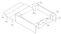
The turnover process of second embodiment below will be described, please be extremely shown in Figure 6 with reference to Fig. 1 and Fig. 3 simultaneously.This turns down the process block diagram for the utility model package lining structure second embodiment Fig. 4; Fig. 5 is the utility model package lining structure second embodiment first side plate turnover block diagram as a result; Fig. 6 turns down another block diagram of process for the utility model package lining structure second embodiment, and Fig. 7 turns down block diagram as a result for the utility model package lining structure second embodiment.The utility model second embodiment is on the first embodiment basis; Again first epipleural 22 is turned down along the first surface 11 of the 7th broken line 57 to base plate 10; The angle of turnover is an an angle of 90 degrees, and then that first interior plate 23 is folding along the 8th broken line 58, folding angle also is an an angle of 90 degrees.By this, first interior plate 22 forms stepped naturally, and the result who has after one group of front end protrusion 231 and rear end protrusion 232, the first side plates turn down is as shown in Figure 5.Like this; After 30 turnovers of second side plate, front end protrusion 231 can withhold second interior plate 33, and the rear end protrusion can withhold main thing to be packaged; Make that the position of second interior plate 33 and main thing to be packaged is relatively fixing, reduce impaired because of rocking the packing material that causes.
Under request in person simultaneously with reference to figure 8 to shown in Figure 9, Fig. 8 is the utility model package lining structure the 3rd embodiment plane outspread drawing, Fig. 9 turns down block diagram as a result for the utility model package lining structure the 3rd embodiment.The 3rd embodiment and second embodiment are similar, and the 3rd embodiment and the second embodiment difference part below will be described, the 3rd embodiment and the second embodiment something in common will repeat no more.
In order to reduce the damage that packing material causes because of vibrations in transit, in the 3rd embodiment, on the base plate 10 and first interior plate 23, also cut one group second and cut mouth 25; Same, for attractive in appearance and stable, this group second can be set cut the equal in length of mouth 25 and be parallel to each other; And; Second cuts mouthfuls 25 the direction and first that cuts cuts mouthfuls 24 and is parallel to each other, and second cuts mouth 25 cuts along the base plate 10 and first interior plate 23 from base plate 10, and its length is exceeded to be no more than first interior plate 23; The one group of line that is parallel to each other that connection second is cut mouthful 25 end points is defined as the 9th broken line 59 and the tenth broken line 510 respectively; Respectively along first surface 11 turnovers to base plate 10 of the 9th broken line 59, the tenth broken line 510, the angle of turnover is an angle of 90 degrees, the intersection vertical folding after will turning down again with second interior plate 23, base plate 10; Form one group of step-like shockproof boss 70 by this, the result is as shown in Figure 9 in turnover.By this, shockproof boss 70 forms the support platform of main thing to be packaged, makes to have certain bumper and absorbing shock space between main thing to be packaged and the base plate 10, can effectively reduce the damage that because of vibrations packing material is caused in transit.It should be noted that second cuts mouthfuls 25 cut position and cutoff length etc. and can make corresponding adjustment according to the size of main thing to be packaged, weight, shape etc., the utility model is not done concrete restriction to this.
In sum; But the difference of knowledge capital utility model and prior art is the utility model and on base plate, cuts baffle plate and baffle plate is turned down; With first side plate, the turnover of second side plate, center on base plate by baffle plate, first side plate and the turnover of second side plate, again to form the package lining box.
Can solve the problem that the chimeric each other assembly program of existing in prior technology multi-disc cardboard is loaded down with trivial details and assembling is difficult through this technological means; And then reach the assembling process of simplifying the package lining structure, need can not constitute the technological effect of package lining box through loaded down with trivial details package program.
More than lift preferred embodiment; Purpose, technical scheme and advantage to the utility model have been carried out further explain, it should be understood that the above is merely the preferred embodiment of the utility model; Not in order to restriction the utility model; All within the spirit and principle of the utility model, any modification of being done, be equal to replacement, improvement etc., all should be included within the protection domain of the utility model; The interest field that the utility model is advocated should be as the criterion so that the utility model application scope is said, but not only limits to the foregoing description.