CN202491901U - Power-assisted control mechanism of electric bicycle - Google Patents
Power-assisted control mechanism of electric bicycle Download PDFInfo
- Publication number
- CN202491901U CN202491901U CN2012200103678U CN201220010367U CN202491901U CN 202491901 U CN202491901 U CN 202491901U CN 2012200103678 U CN2012200103678 U CN 2012200103678U CN 201220010367 U CN201220010367 U CN 201220010367U CN 202491901 U CN202491901 U CN 202491901U
- Authority
- CN
- China
- Prior art keywords
- crankshaft
- electric bicycle
- coil
- control mechanism
- ring
- Prior art date
- Legal status (The legal status is an assumption and is not a legal conclusion. Google has not performed a legal analysis and makes no representation as to the accuracy of the status listed.)
- Expired - Fee Related
Links
- 230000005540 biological transmission Effects 0.000 claims description 11
- 238000009434 installation Methods 0.000 description 5
- 238000000034 method Methods 0.000 description 2
- 230000009286 beneficial effect Effects 0.000 description 1
- 238000010586 diagram Methods 0.000 description 1
- 230000000694 effects Effects 0.000 description 1
- 230000002093 peripheral effect Effects 0.000 description 1
Images


Classifications
-
- B—PERFORMING OPERATIONS; TRANSPORTING
- B62—LAND VEHICLES FOR TRAVELLING OTHERWISE THAN ON RAILS
- B62M—RIDER PROPULSION OF WHEELED VEHICLES OR SLEDGES; POWERED PROPULSION OF SLEDGES OR SINGLE-TRACK CYCLES; TRANSMISSIONS SPECIALLY ADAPTED FOR SUCH VEHICLES
- B62M3/00—Construction of cranks operated by hand or foot
- B62M3/003—Combination of crank axles and bearings housed in the bottom bracket
-
- B—PERFORMING OPERATIONS; TRANSPORTING
- B62—LAND VEHICLES FOR TRAVELLING OTHERWISE THAN ON RAILS
- B62M—RIDER PROPULSION OF WHEELED VEHICLES OR SLEDGES; POWERED PROPULSION OF SLEDGES OR SINGLE-TRACK CYCLES; TRANSMISSIONS SPECIALLY ADAPTED FOR SUCH VEHICLES
- B62M6/00—Rider propulsion of wheeled vehicles with additional source of power, e.g. combustion engine or electric motor
- B62M6/40—Rider propelled cycles with auxiliary electric motor
- B62M6/45—Control or actuating devices therefor
- B62M6/50—Control or actuating devices therefor characterised by detectors or sensors, or arrangement thereof
Landscapes
- Engineering & Computer Science (AREA)
- Chemical & Material Sciences (AREA)
- Combustion & Propulsion (AREA)
- Transportation (AREA)
- Mechanical Engineering (AREA)
- Arrangement Or Mounting Of Propulsion Units For Vehicles (AREA)
Abstract
Description
技术领域 technical field
本实用新型与电动自行车有关,特别是有关于一种电动自行车的助力控制机构。The utility model relates to electric bicycles, in particular to a booster control mechanism for electric bicycles.
背景技术 Background technique
传统的电动自行车都是通过骑乘者的踩踏力量搭配电动机提供的辅助动力而获得前进的动力,使得电动自行车不会对骑乘者的体力造成太大的负荷,并可让骑乘者在休闲的余也能达到健身的目的。Traditional electric bicycles obtain forward power through the pedaling force of the rider combined with the auxiliary power provided by the motor, so that the electric bicycle will not cause too much load on the physical strength of the rider, and allows the rider to enjoy leisure time. The rest can also achieve the purpose of fitness.
然而在现有设计中,大齿盘与后轮的位置会分别安装一组传感器,用以分别感测大齿盘的转速及后轮的转速,由此,微电脑即可根据两组传感器所感测到的转速大小来控制助力大小或通过变速器来进行变速换档动作,但是在两组传感器的安装过程中,很容易受到空间限制而造成安装上的麻烦与不便。However, in the existing design, a set of sensors are respectively installed at the position of the large chainring and the rear wheel to sense the rotational speed of the large chainring and the rotational speed of the rear wheel respectively. The size of the speed can be controlled to control the size of the power assist or the transmission can be used to change gears. However, during the installation of the two sets of sensors, it is easy to be troubled and inconvenient due to space constraints.
实用新型内容 Utility model content
本实用新型的主要目的在于提供一种电动自行车的助力控制机构,其能简便地完成两个传感器的安装,以便根据所感测到的车速来计算出所需要的助力大小。The main purpose of the present utility model is to provide a booster control mechanism of an electric bicycle, which can easily complete the installation of two sensors, so as to calculate the required booster according to the sensed vehicle speed.
本实用新型的次一目的在于提供一种电动自行车的助力控制机构,其能根据所感测到的车速来进行换档动作。The second object of the present utility model is to provide a booster control mechanism for an electric bicycle, which can perform gear shifting according to the sensed vehicle speed.
为达成上述目的,本实用新型一种电动自行车的助力控制机构,其特征在于,包含有:一曲柄组,具有一曲柄轴、二曲柄,以及一挡环,该两曲柄设于该曲柄轴的两端,该挡环套设固定于该曲柄轴而与该曲柄轴同步转动;In order to achieve the above object, the utility model is a power-assisted control mechanism of an electric bicycle, which is characterized in that it includes: a crank set with a crank shaft, two cranks, and a retaining ring, and the two cranks are arranged on the crank shaft At both ends, the retaining ring is sleeved and fixed on the crankshaft to rotate synchronously with the crankshaft;
一大齿盘,套设于该曲柄组的曲柄轴;A large chainring is sleeved on the crankshaft of the crankset;
一单向器,设于该大齿盘与该曲柄组的曲柄轴之间且与其中一该曲柄组接,受该曲柄的驱动而带动该大齿盘作单向转动;以及a one-way device, arranged between the large chainring and the crank shaft of the crankset and connected to one of the cranksets, driven by the crank to drive the large chainring to rotate in one direction; and
一控制装置,具有一安装座、一第一传感器、一第二传感器,以及一微电脑,该安装座连接于该曲柄轴,该第一传感器设于该安装座且相对该大齿盘,用以感测该大齿盘的转速,该第二传感器设于该安装座且相对该曲柄组的挡环,用以通过该挡环来感测该曲柄轴的转速,该微电脑电性连接该第一、第二传感器,根据该第一、第二传感器所感测到的结果来控制助力大小。A control device has a mounting base, a first sensor, a second sensor, and a microcomputer, the mounting base is connected to the crankshaft, the first sensor is arranged on the mounting base and opposite to the large chainring, for Sensing the rotation speed of the large chainring, the second sensor is arranged on the mounting seat and opposite to the stop ring of the crankset, and is used to sense the rotation speed of the crankshaft through the stop ring, and the microcomputer is electrically connected to the first , the second sensor, controlling the magnitude of the power assist according to the results sensed by the first and second sensors.
其中该单向器具有一棘齿环、一棘轮座,以及多个棘爪,该棘齿环连接该大齿盘,该棘轮座连接该曲柄,各该棘爪的一端枢设于该棘轮座,另一端卡接于该棘齿环。Wherein the one-way device has a ratchet ring, a ratchet seat, and a plurality of pawls, the ratchet ring is connected to the large toothed plate, the ratchet seat is connected to the crank, and one end of each pawl is pivotally arranged on the ratchet seat, The other end is fastened to the ratchet ring.
其中该大齿盘具有一齿盘本体,一第一固定环,以及一第二固定环,该齿盘本体被该第一、第二固定环夹持在中间且供该链条绕设,该第一固定环具有一内卡槽,该单向器的棘齿环具有一外卡槽,该内、外卡槽之间经由一卡合块而组装在一起,使得该大齿盘可被该单向器所驱动。Wherein the large chainring has a toothed body, a first fixed ring, and a second fixed ring, the toothed body is clamped in the middle by the first and second fixed rings and the chain is wound around, the first A fixed ring has an inner slot, and the ratchet ring of the one-way device has an outer slot, and the inner and outer slots are assembled together through an engaging block, so that the large toothed plate can be used by the single Driven by the device.
其中该大齿盘的第一固定环相对于该第一传感器的一侧面设有多个磁铁。Wherein the first fixed ring of the large toothed disc is provided with a plurality of magnets on a side opposite to the first sensor.
其中一该曲柄具有一外卡槽,该单向器的棘齿座具有一内卡槽,该外、内卡槽之间经由一卡合块而组装在一起,使得该单向器可被该曲柄所驱动。One of the cranks has an outer card slot, and the ratchet seat of the one-way device has an inner card slot, and the outer and inner card slots are assembled together through an engaging block, so that the one-way device can be used by the one-way device. driven by the crank.
其中该曲柄轴的挡环相对于该第二传感器的一侧面设有多个磁铁。Wherein the retaining ring of the crankshaft is provided with a plurality of magnets on a side opposite to the second sensor.
其中该曲柄轴设有一发电装置,受该曲柄轴的驱动而产生电流。Wherein the crankshaft is provided with a power generating device, which is driven by the crankshaft to generate electric current.
其中该发电装置具有一线圈座、二轴承、一线圈、一磁铁,以及一电线,该线圈座套设于该曲柄轴,该两轴承设于该曲柄轴与该线圈座之间,使得该曲柄轴能相对该线圈座转动,该线圈固定于该线圈座,该磁铁固定于该曲柄轴且相对于该线圈,受该曲柄轴的带动而绕着该线圈旋转,该电线连接该线圈,用以将该线圈所产生的感应电流传送出去。Wherein the generating device has a coil seat, two bearings, a coil, a magnet, and an electric wire, the coil seat is sleeved on the crank shaft, and the two bearings are arranged between the crank shaft and the coil seat, so that the crank The shaft can rotate relative to the coil seat, the coil is fixed on the coil seat, the magnet is fixed on the crank shaft and relative to the coil, and is driven by the crank shaft to rotate around the coil, and the wire is connected to the coil for The induced current generated by the coil is sent out.
其中该感测装置的安装座固定于该发电装置的线圈座。Wherein the mounting seat of the sensing device is fixed on the coil seat of the generating device.
包括有一变速器,通过该控制装置的微电脑与该控制装置的第一、第二传感器电性连接,使得该变速器可分别根据该第一、第二传感器所感测到的结果来进行换挡动作。It includes a transmission, and the microcomputer of the control device is electrically connected with the first and second sensors of the control device, so that the transmission can perform gear shifting according to the results sensed by the first and second sensors.
其中该变速器包括一换档驱动器、一后拨链器,以及一变速线,该换档驱动器用以设置于该电动自行车的一车架,该后拨链器用以设于该电动自行车的一后轮,该变速线连接该换档驱动器及该后拨链器。Wherein the transmission includes a shift driver, a rear derailleur, and a speed change cable, the shift driver is used to be arranged on a frame of the electric bicycle, and the rear derailleur is used to be arranged on a rear of the electric bicycle wheel, the shifting cable is connected to the shift driver and the rear derailleur.
其中该控制装置的微电脑通过该第一传感器所感测到的大齿盘的转速来换算成车速而计算出助力大小。Wherein the microcomputer of the control device converts the rotational speed of the large chainring sensed by the first sensor into the vehicle speed to calculate the magnitude of the power assist.
本实用新型的有益效果是:本实用新型的助力控制机构将两个传感器通过该安装座而安装于该曲柄轴上,可增加安装上的便利性,并且能够通过感测该大齿盘的转速大小及该曲柄轴的转速大小而取得行车速度及踏力大小的数据,以便计算出所需要的助力大小。The beneficial effects of the utility model are: the booster control mechanism of the utility model installs two sensors on the crankshaft through the mounting seat, which can increase the convenience of installation, and can sense the rotation speed of the large chainring size and the size of the rotational speed of the crankshaft to obtain the data of the driving speed and the size of the pedaling force, so as to calculate the required power assist size.
附图说明 Description of drawings
以下配合附图列举以下较佳实施例,用以对本实用新型的结构及功效进行详细说明,其中:The following preferred embodiments are listed below in conjunction with the accompanying drawings, in order to describe the structure and effect of the present utility model in detail, wherein:
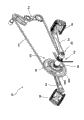
图1为应用本实用新型一较佳实施例的自行车的平面图。Fig. 1 is a plan view of a bicycle applying a preferred embodiment of the present invention.
图2为应用本实用新型一较佳实施例的自行车在另一方向的局部平面图。Fig. 2 is a partial plan view in another direction of a bicycle applying a preferred embodiment of the present invention.
图3为本实用新型一较佳实施例的立体图。Fig. 3 is a perspective view of a preferred embodiment of the present invention.
图4为本实用新型一较佳实施例的局部立体分解图。Fig. 4 is a partial three-dimensional exploded view of a preferred embodiment of the present invention.
图5为图4的局部放大图,主要显示曲柄、大齿盘的第一固定环,以及单向器之间的关系。Fig. 5 is a partially enlarged view of Fig. 4, mainly showing the relationship between the crank, the first fixed ring of the large toothed disc, and the one-way device.
图6为本实用新型一较佳实施例所提供的单向器的端视图。Fig. 6 is an end view of the one-way device provided by a preferred embodiment of the present invention.
图7为本实用新型一较佳实施例的组合剖视图。Fig. 7 is a combined sectional view of a preferred embodiment of the present invention.
图8为本实用新型一较佳实施例的方块图。Fig. 8 is a block diagram of a preferred embodiment of the present invention.
具体实施方式 Detailed ways
请先参阅图1,为应用本发明一较佳实施例的电动自行车10,图中所示的电动自行车10包含有一车架12、一设于车架12前端的前轮14,以及一设于车架12后端的后轮16。请再参阅图2至图5,为本发明一较佳实施例的助力控制机构18,包含有一变速器20、一曲柄组30、一发电装置40、一大齿盘50、一单向器60、一链条70,以及一控制装置80。Please refer to Fig. 1 first, for applying the
变速器20具有一换档驱动器22、一后拨链器24,以及一变速线26,其中,换档驱动器22可依实际需要设于车架12的五通管122、后上叉124或后下叉126,在此以五通管122为例,如图1及图2所示;后拨链器24设于后轮16的花鼓162;变速线26连接换档驱动器22及后拨链器24。由此,变速器20可受换档驱动器24的驱动而带动后拨链器22进行换档动作。The
曲柄组30具有一曲柄轴32、二曲柄34,以及一挡环36,其中,曲柄轴32可旋转地穿设于车架12内;各曲柄34的内端固定于曲柄轴32的一端,各曲柄34的外端供一踏板38安装,此外,曲柄34的内端具有一第一外卡槽342;挡环36套设固定于曲柄轴32而可与曲柄轴32同步转动,且挡环36的一侧面设有多个磁铁362。The
发电装置40具有一线圈座41、二轴承42、一线圈43、一磁铁44,以及一电线45,如图7所示,线圈座41套设于曲柄轴32;该两轴承42设于曲柄轴32与线圈座41之间,使得曲柄轴32能相对线圈座41旋转;线圈43固定于线圈座41的内周面;磁铁44固定于曲柄轴32且相对于线圈43;电线45以其一端连接线圈84,另一端连接于需要充电的装置,如电池或大灯。由此,曲柄轴32在转动时便会同步带动磁铁44绕着线圈43旋转,如此便能产生磁场变化而让线圈43产生感应电流,接着即可利用电线45将线圈43所产生的感应电流传送出去。The
大齿盘50套设于曲柄轴32且具有一齿盘本体52,一第一固定环54,以及一第二固定环56,其中,齿盘本体52被第一、第二固定环54、56夹持在中间,第一固定环54具有一第一内卡槽542,如图5所示,第二固定环56的一侧面设有多个磁铁562。The
如图5及图6所示,单向器60具有一棘齿环61、一棘轮座62,以及多个棘爪63,棘齿环61具有一第二外卡槽612,棘轮座62具有一第二内卡槽622,各棘爪63位于棘齿环61及棘轮座62之间,并以其一端枢设于棘轮座62,另一端卡接于棘齿环61。单向器60的第二外卡槽612与大齿盘50的第一固定环54的第一内卡槽542之间设有一第一卡合块64,单向器60的第二内卡槽622与曲柄34的第一外卡槽342之间设有一第二卡合块65,由此,单向器60可受曲柄34的驱动而通过第一固定环54来带动大齿盘50作单向转动,一旦大齿盘50的转速高于曲柄34的转速时,单向器60便会解除两者之间的传动。As shown in Figure 5 and Figure 6, the one-
链条70绕设于后轮16的后花鼓162、变速器20的后拨链器24,以及大齿盘50的齿盘本体52,用以传动后轮16转动。The
控制装置80具有一安装座82、一第一传感器84、一第二传感器86,以及一微电脑88,如图7及图8所示,安装座82固定于发电装置40的线圈座41而套设于曲柄轴32;第一传感器84为霍尔传感器,是设于安装座82且与设置在大齿盘50的磁铁562互相对应,用以通过磁铁562所产生的磁场变化来感测大齿盘50的转速;第二传感器86为霍尔传感器,是设于安装座82且与设置在曲柄组30的挡环36的磁铁362互相对应,由于挡环36与曲柄轴32同步转动,所以能够通过磁铁362所产生的磁场变化来感测曲柄轴32的转速;微电脑88电性连接第一、第二传感器84、86,并与变速器20的后拨链器24电性连接,使得微电脑88能分别根据第一、第二传感器84、86所感测到的结果来控制助力大小及变速换挡动作。The
以上为本发明的助力控制机构18的详细结构,以下再就本发明的操作过程及特色进行说明。The above is the detailed structure of the
当骑乘者施力踩踏该两踏板38来驱动曲柄组30旋转时,通过单向器60的驱动,大齿盘50会开始旋转且通过链条70来带动后花鼓162同步旋转,以驱动后轮16转动而让电动自行车10能够顺利前进。在大齿盘50及曲柄轴32旋转的过程中,第一、第二传感器84、86会通过不同位置的磁铁562、362所产生的磁场变化来感测大齿盘50及曲柄轴32的转速,并将所感测到的转速值传送至微电脑88,微电脑88即可通过第一、第二传感器84、86所感测到的结果来换算成行车速度及踏力大小,以便计算出所需输出的助力大小。When the rider steps on the two
另一方面,当大齿盘50及曲柄轴32的转速均保持在大于20RPM的情况下,骑乘者除了可以利用手动方式进行换档之外,亦可通过微电脑90的设定来进行自动换档,但是当第一传感器84感测到大齿盘50的转速低于20RPM时,或者当第二传感器86感测到曲柄轴32的转速低于20RPM时,微电脑90便会控制变速器20的后拨链器24无法进行换档动作,此时的骑乘者不管利用手动操控或通过微电脑90的自动控制都无法进行换档,以确保变速线维持在适当的松紧度,同时又能避免发生落链的状况。On the other hand, when the rotating speeds of the
综上所述,本实用新型的助力控制机构18将两个传感器84,86同时安装于曲柄轴32而简便地完成安装,以便根据所感测到的行车速度及踏力大小来控制助力大小及进行换档动作。In summary, the power
Claims (12)
Priority Applications (1)
| Application Number | Priority Date | Filing Date | Title |
|---|---|---|---|
| CN2012200103678U CN202491901U (en) | 2012-01-11 | 2012-01-11 | Power-assisted control mechanism of electric bicycle |
Applications Claiming Priority (1)
| Application Number | Priority Date | Filing Date | Title |
|---|---|---|---|
| CN2012200103678U CN202491901U (en) | 2012-01-11 | 2012-01-11 | Power-assisted control mechanism of electric bicycle |
Publications (1)
| Publication Number | Publication Date |
|---|---|
| CN202491901U true CN202491901U (en) | 2012-10-17 |
Family
ID=46998138
Family Applications (1)
| Application Number | Title | Priority Date | Filing Date |
|---|---|---|---|
| CN2012200103678U Expired - Fee Related CN202491901U (en) | 2012-01-11 | 2012-01-11 | Power-assisted control mechanism of electric bicycle |
Country Status (1)
| Country | Link |
|---|---|
| CN (1) | CN202491901U (en) |
Cited By (6)
| Publication number | Priority date | Publication date | Assignee | Title |
|---|---|---|---|---|
| CN105314026A (en) * | 2014-08-01 | 2016-02-10 | 福特全球技术公司 | Electric bicycle |
| EP3050790A1 (en) * | 2015-01-30 | 2016-08-03 | Ncte Ag | Cordless speed, torque and power sensor for bicycles |
| CN106364622A (en) * | 2016-10-18 | 2017-02-01 | 无锡富乐力科技有限公司 | Integrated electric power assisting device for bicycle |
| CN107588787A (en) * | 2016-07-07 | 2018-01-16 | 翌能科技股份有限公司 | Rotary encoder and operation method thereof and bicycle with rotary encoder |
| CN109436173A (en) * | 2018-09-29 | 2019-03-08 | 隋启合 | The electric bicycle of chain wheel installation flywheel |
| EP3666635A1 (en) * | 2018-12-13 | 2020-06-17 | Yueh-Han Li | Bicycle with a power assist transmission device |
-
2012
- 2012-01-11 CN CN2012200103678U patent/CN202491901U/en not_active Expired - Fee Related
Cited By (9)
| Publication number | Priority date | Publication date | Assignee | Title |
|---|---|---|---|---|
| CN105314026A (en) * | 2014-08-01 | 2016-02-10 | 福特全球技术公司 | Electric bicycle |
| EP3050790A1 (en) * | 2015-01-30 | 2016-08-03 | Ncte Ag | Cordless speed, torque and power sensor for bicycles |
| WO2016119958A1 (en) * | 2015-01-30 | 2016-08-04 | Ncte Ag | Cableless rotational speed, torque and output sensor for bicycles |
| CN107588787A (en) * | 2016-07-07 | 2018-01-16 | 翌能科技股份有限公司 | Rotary encoder and operation method thereof and bicycle with rotary encoder |
| CN106364622A (en) * | 2016-10-18 | 2017-02-01 | 无锡富乐力科技有限公司 | Integrated electric power assisting device for bicycle |
| CN106364622B (en) * | 2016-10-18 | 2022-05-24 | 无锡富乐力科技有限公司 | Integrated electric power assisting device for bicycle |
| CN109436173A (en) * | 2018-09-29 | 2019-03-08 | 隋启合 | The electric bicycle of chain wheel installation flywheel |
| EP3666635A1 (en) * | 2018-12-13 | 2020-06-17 | Yueh-Han Li | Bicycle with a power assist transmission device |
| US11292553B2 (en) * | 2018-12-13 | 2022-04-05 | Yueh-Han Li | Bicycle with a power assist transmission device |
Similar Documents
| Publication | Publication Date | Title |
|---|---|---|
| CN102753429B (en) | Motor with integrated torque sensor | |
| CN114423675B (en) | Electric Assisted Vehicle Propulsion Systems | |
| CN202491901U (en) | Power-assisted control mechanism of electric bicycle | |
| US8376110B2 (en) | Bicycle hub assembly | |
| TWI767247B (en) | Electrically-assisted pedal cycles | |
| US20160303961A1 (en) | Integrated Electric Bicycle Drive System | |
| US20110303474A1 (en) | Hybrid drive for an electric bicycle | |
| TWI552917B (en) | Electric bicycle outside the transmission mechanism | |
| TW202214454A (en) | Electric vehicle, method for driving vehicle and computer-readable medium thereof | |
| CN107128126A (en) | Bicycle hub assembly and bicycle transmission system | |
| CN102933453A (en) | Bicycle with electrical drive system | |
| TW201836908A (en) | Hybrid powertrain for a pedal vehicle, control unit therefor, pedal vehicle | |
| CN103963913B (en) | Automatic stepless speed change device for bicycle | |
| CN107054544A (en) | Bicycle Drive Unit | |
| CN108688761A (en) | Clutch type electric driving device for bicycle | |
| KR101643912B1 (en) | A chain-free bicycle using auto-generator with accelator | |
| CN210101921U (en) | Electric Auxiliary Drive Units for Bicycles | |
| CN201390360Y (en) | Power car dual drive | |
| CN110001863A (en) | Speed-change control device and electric shift system | |
| CN104276249B (en) | The even power assisted pedal stroke car of intelligence | |
| CN201784784U (en) | Compound driven tricycle structure | |
| CN201777369U (en) | Mechanical energy storage type semi-automatic bicycle | |
| CN210681050U (en) | Bicycle speed change device, speed change bicycle | |
| CN114735125A (en) | Control device for human-powered vehicle | |
| TWI646016B (en) | Electric assist bicycle drive |
Legal Events
| Date | Code | Title | Description |
|---|---|---|---|
| C14 | Grant of patent or utility model | ||
| GR01 | Patent grant | ||
| CF01 | Termination of patent right due to non-payment of annual fee | ||
| CF01 | Termination of patent right due to non-payment of annual fee |
Granted publication date: 20121017 Termination date: 20180111 |