CN202491529U - Printer - Google Patents
Printer Download PDFInfo
- Publication number
- CN202491529U CN202491529U CN2012200273429U CN201220027342U CN202491529U CN 202491529 U CN202491529 U CN 202491529U CN 2012200273429 U CN2012200273429 U CN 2012200273429U CN 201220027342 U CN201220027342 U CN 201220027342U CN 202491529 U CN202491529 U CN 202491529U
- Authority
- CN
- China
- Prior art keywords
- power supply
- supply adaptor
- slot
- printer
- cavity
- Prior art date
- Legal status (The legal status is an assumption and is not a legal conclusion. Google has not performed a legal analysis and makes no representation as to the accuracy of the status listed.)
- Expired - Fee Related
Links
Images


Landscapes
- Accessory Devices And Overall Control Thereof (AREA)
Abstract
The utility model discloses a printer, comprising a shell, a power adapter arranged in the shell and a gland. A power adapter cavity seat is arranged at the bottom of the shell and includes a slot for accommodating the main body of the power adapter, a concave cavity for accommodating the cable of the power adapter and a wire passage for communicating the slot and the concave cavity. Openings of both the slot and the concave cavity face toward the outside of the shell, and the cavity wall of the power adapter cavity seat is provided with a first clamping slot and a second clamping slot. The gland extends at least partially onto the openings of both the concave cavity and the slot and includes a first clamping hook cooperating with the first clamping slot in a clamping way and a second clamping hook cooperating with the second clamping slot in a clamping way. Power adapters of similar boundary dimensions and different models can be arranged in the printer provided by the utility model, and thus adaptability of the printer to power adapters is improved.
Description
Technical field
The utility model relates to a kind of printer.
Background technology
After printer need use power supply adaptor to convert 220V high-voltage power supply commonly used to LVPS stable about 5V to 24V, can operate as normal.Printer uses power supply adaptor that built-in and external dual mode is arranged, and power supply adaptor all adopts external occupation mode usually, separates placement with printer, and this occupation mode is not only extra to take up room, and also inconvenient when mobile printer.
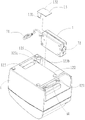
Japan Patent JP2001018481 provides a kind of printer; As shown in Figure 1; This printer is placed on power supply adaptor 10 ' in the casing 1a of printer 1 '; And using the gland (not shown) power supply adaptor 10 ' to be enclosed in the casing 1a of printer, the output interface 18 ' of power supply adaptor 10 ' is pegged graft with the power interface of printer 1 ' 19 ', is the printer power supply.Through grab on the power supply adaptor 10 ' 23 ' and the interior claw 24 ' snap fit of casing 1a, power supply adaptor 10 ' is fixed in the casing 1a of printer 1 '; When outside pull power supply adaptor 10 '; Because the claw 24 ' in the casing 1a has elasticity; Pressurized deforms; The grab 23 ' of power supply adaptor 10 ' breaks away from claw 24 ', and power supply adaptor 10 ' can be pulled out in the casing 1a of printer 1 ', the power supply adaptor that can more renew this moment.
Above-mentioned printer is fixedly connected with printer in order to make power supply adaptor, and grab need be set on power supply adaptor, so this printer need use special-purpose power supply adaptor, and is poor for applicability.
The utility model content
The purpose of the utility model is to provide a kind of printer that fit structure need be set at power supply adaptor, to improve the adaptability of printer to power supply adaptor.
For this reason; The utility model provides a kind of printer; Comprise housing, be installed on power supply adaptor in the housing and the gland that is used for fixing power supply adaptor, wherein, the bottom of housing is provided with power supply adaptor chamber seat; Power supply adaptor chamber seat comprise the main body of holding power supply adaptor slot, hold power supply adaptor cable cavity and be communicated with slot and the passing channel of cavity; Wherein, slot and cavity uncovered all towards the bottom outside of housing, the chamber wall of power supply adaptor chamber seat is provided with first draw-in groove and second draw-in groove; Gland extends at least in part on slot uncovered and on cavity uncovered, extends at least in part, gland also comprise with first grab of the first draw-in groove snap fit and with second grab of the second draw-in groove snap fit.
Further, above-mentioned slot and the cavity layout that is rectangular in shape.
Further, above-mentioned slot and cavity are the yi word pattern layout.
Further, the uncovered and slot of above-mentioned gland sealing cavity is uncovered.
Further, the inside of above-mentioned housing is provided with the control panel chamber seat that holds control panel, and the chamber wall of control panel chamber seat is provided with first opening that the interface that supplies control panel exposes and second opening that is communicated with cavity.
Further, the chamber wall of above-mentioned slot is provided with the 3rd opening that the input of the main body of power supply source adapter exposes.
Further, above-mentioned first draw-in groove and second draw-in groove are positioned at the left and right sides of passing channel.
Further, above-mentioned first grab comprises the card arm buckling body terminal with being positioned at the card arm that extends perpendicular to the main body of gland, and second grab is the coupler body in L type cross section.
In the printer that the utility model provides; Through on lower house, being provided with and suitable slot and the cavity of power supply adaptor appearance and size; And use gland and slot and/or cavity snap fit; Can power supply adaptor be fixed on lower house inside, fit structure need be set on power supply adaptor can realize the fixed-site of power supply adaptor, therefore in printer; The printer that the utility model provides can be installed the power supply adaptor of the approximate different model of appearance and size, has improved the adaptability of printer to power supply adaptor.
Except top described purpose, characteristic and advantage, other purpose, characteristic and the advantage that the utlity model has are with combining accompanying drawing to do further detailed explanation.
Description of drawings
Constitute the preferred embodiment that the part of this specification, the accompanying drawing that is used for further understanding the utility model show the utility model, and be used for explaining the principle of the utility model with specification.Among the figure:
Fig. 1 is the structural representation of printer when power supply adaptor is installed of prior art;
Fig. 2 is the structural representation of printer first embodiment that provides of the utility model;
Axonometric drawing when Fig. 3 is bottom-up placement of printer shown in Figure 2;
Fig. 4 a is the lower house bottom of a printer shown in Figure 2 structural representation during towards held;
The structural representation of Fig. 4 b when to be that the lower house of printer shown in Figure 2 is bottom-up place;
Fig. 5 is the work sketch map of printer when changing power supply adaptor shown in Figure 2; And
Fig. 6 is the structural representation of the lower house of printer second embodiment that provides of the utility model.
Description of reference numerals
1 lower house, 2 upper shells
3 print components, 4 cutter assemblies
5 paper storehouses, 6 control panels
7 power supply adaptors, 10 jointed shafts
31 printheads 32 are printed rubber roll
41 quiet sword 42 moving swords
11 control panel chamber seats, 12 power supply adaptor chamber seats
13 glands, 111 first openings
112 second openings, 113 support columns
121 the 3rd openings, 122 slots
123 chambeies, 7 power supply adaptors
71 output lines, 72 inputs
The 123a first draw-in groove 123b second draw-in groove
125 passing channels, 131 first grabs
132 second grabs, 61 communication interfaces.
The specific embodiment
Embodiment to the utility model is elaborated below in conjunction with accompanying drawing, but the multitude of different ways that the utility model can be defined by the claims and cover is implemented.
Fig. 2 is the structural representation of printer first embodiment that provides of the utility model, the axonometric drawing when Fig. 3 is bottom-up placement of printer shown in Figure 2.As shown in Figures 2 and 3, printer comprises lower house 1, upper shell 2, print components 3, cutter assembly 4, paper storehouse 5 and control panel 6, and power supply adaptor 7.
Wherein, upper shell 2 is hinged on the lower house 1 through jointed shaft 10, can be with respect to lower house 1 folding.In upper shell 2 and the interior volume that lower house 1 forms, be provided with paper storehouse 5, be used to hold printing paper P.
Along printing paper P throughput direction, be provided with print components 3 in 5 downstream, paper storehouse, be used on printing paper P, printing predefined print What.Print components 3 can be the hot print assembly, can be print components such as pin type, ink-jet, laser also, and print components 3 is hot print assemblies in the present embodiment; Comprise printhead 31 and print rubber roll 32, wherein printhead 31 is fixed on the lower house 1, prints rubber roll 32 and is fixed on the upper shell 2; When printer upper shell 2 is closed with respect to lower house 1; Printhead 31 is printed rubber roll 32 and under transmission system drives, is rotated with to print rubber roll 32 tangent, drive paper between printhead 31 and printing rubber roll 32 to print components 3 downstream transmission; Simultaneously, printhead 31 prints on printing paper.Because print components such as traditional pin type, ink-jet, laser are provided with form and are well known to those skilled in the art, and its setting is little with relevance of the present invention, therefore repeats no more.
Be provided with cut paper assembly 4 in print components 3 downstream, be used for the paper after printing is cut off.Cut paper assembly 4 comprises quiet sword 41 and moving sword 42, and wherein quiet sword 41 is fixedly installed on the upper shell 2, is positioned at the downstream of printhead 31 along the paper delivery direction; Moving sword 42 is provided with on the lower house 1, is positioned at the downstream of printing rubber roll 32 along the paper delivery direction.When the relative lower house of printer upper shell 21 is closed, pass through between the driven sword 42 of printing paper P and the quiet sword 41, move the quiet relatively sword 41 of sword 42 and do linear reciprocating motion, can cut off paper, it is separated with paper roll.
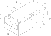
Fig. 4 a is the lower house bottom of a printer shown in Figure 2 structural representation during towards held, the structural representation when Fig. 4 b is bottom-up placement of lower house of printer shown in Figure 2.Shown in Fig. 4 a and Fig. 4 b, lower house 1 comprises control panel chamber seat 11, power supply adaptor chamber seat 12 and gland 13.
Control panel chamber seat 11 is used to hold control panel 6, offers first opening 111 and second opening 112 on the chamber wall of control panel chamber seat 11.Wherein, control panel chamber seat 11 is used to make the control panel 6 and printer external communications that is installed in control panel chamber seat 11 inside, and preferably, referring to the coordinate direction among Fig. 4 a, first opening 111 is positioned at the rear of control panel chamber seat 11; Second opening 112 is used to make control panel chamber seat 11 to be communicated with power supply adaptor chamber seat 12, and it is positioned at the position of matching with power supply adaptor chamber seat 12; In addition, seat 11 set inside have installation portion in the control panel chamber, are used for fixing installation and control plate 6, and in the present embodiment, installation portion is a plurality of support columns 113 that extend along the printer short transverse.
Power supply adaptor chamber seat 12 is used to hold power supply adaptor 7, offers the 3rd opening 121 on the chamber wall of power supply adaptor chamber seat 12, is used to make power supply adaptor chamber seat 12 and printer external communications.
Concrete; Power supply adaptor chamber seat 12 comprises slot 122 and cavity 123, and draw-in groove, wherein; Slot 122 is used to hold the main body of power supply adaptor 7; The appearance and size of the main body of its inside dimension and power supply adaptor 7 is suitable, and an end of slot 122 is through the 3rd opening 121 and printer external communications, and the other end is communicated with cavity 123; Cavity 123 is used to hold the output line (cable and assembly thereof) of power supply adaptor 7, and the volume of its volume and output line is suitable, and cavity 123 1 ends are communicated with slot 122, and the other end is communicated with control panel chamber seat 11 through second opening 112 of control panel chamber seat 11; Form passing channel 125 between slot 122 and the cavity 123, cavity 123 is communicated with slot 122 through passing channel 125, and the external diameter of the output line of the width of passing channel 125 and power supply adaptor 7 is suitable; Draw-in groove is included in the first draw-in groove 123a and the second draw-in groove 123b that is provided with on the chamber wall that is positioned at passing channel 125 both sides of power supply adaptor chamber seat 12, is used for and gland 13 snap fit.
Need to prove; The first draw-in groove 123a and the second draw-in groove 123b can be arranged on the chamber wall of slot 122 both sides; Also can be arranged on the chamber wall of cavity 123 both sides, can also two in the draw-in groove one be arranged on the chamber wall of slot 122 1 sides, another is arranged on the chamber wall of cavity 123 1 sides.
The draw-in groove snap fit of gland 13 and power supply adaptor chamber seat 12 is used for sealing at least in part the uncovered of power supply adaptor chamber seat 12, promptly seals the uncovered of slot 122 at least in part and seals the uncovered of cavity 123 at least in part.The material of gland 13 is plastics or rubber-like metal, for the tabular structure of rectangle, has setting thickness, and the width of the width of gland 13 and slot 122 is suitable.
Gland 13 is provided with and the first draw-in groove 123a and corresponding first grab 131 of the second draw-in groove 123b and second grab 132, can perhaps separate with the second draw-in groove 123b snap fit with the first draw-in groove 123a respectively.
Preferably, first grab 131 comprises the card arm buckling body terminal with being positioned at the card arm that extends perpendicular to gland 13 main bodys, and second grab 132 is the coupler body in L type cross section.
In the present embodiment, slot 122 and cavity 123 both L-shaped settings, wherein, slot 122 is arranged side by side along the fore-and-aft direction perpendicular to printer with control panel chamber seat 11, and cavity 123 is arranged side by side with the fore-and-aft direction of control panel chamber seat 11 along printer.
Uncovered being inserted in the slot 122 of the main body of power supply adaptor 7 seat 12 from the power supply adaptor chamber; The cable of power supply adaptor 7 gets in the cavitys 123 through passing channel 125, and first grab 131, second grab 132 of gland 13 are distinguished snap fit with the first draw-in groove 123a and second draw-in groove.At this moment, the input 72 of power supply adaptor 7 is through the external communications of the 3rd opening 121 with printer, and the output line 71 of power supply adaptor 7 is connected with the power interface of control panel 6 through second opening 112 on the control panel chamber seat 11.
At this moment; The chamber wall restriction power supply adaptor 7 of power supply adaptor chamber seat 12 can only move to the direction away from lower house 1 along the vertical direction; Again because first grab 131 of gland 13, second grab 132 are distinguished snap fit with the first draw-in groove 123a and the second draw-in groove 123b; Gland 13 has limited power supply adaptor 7 along away from the moving of the direction of lower house, thereby power supply adaptor 7 is fixed in the power supply adaptor chamber seat 12.
Need to prove; In the present embodiment first opening 111 and the 3rd opening 121 be arranged on the rear of printer; The communication interface 61 of control panel 6 and the input 72 of power supply adaptor 7 are in communication with the outside from the rear of printer, so connection is connected with the interface of computer, the input 72 of power supply adaptor 7 communication interface 61 respectively with the rear of power line from printer with the 220V high voltage source.In other embodiment that the utility model provides; Also can first opening 111 and the 3rd opening 121 be arranged on side or the place ahead of printer, connection is connected with the interface of computer, the input 72 of power supply adaptor 7 communication interface 61 respectively with power line side or the place ahead from printer with the 220V high voltage source like this.
The process that the printer that introducing the utility model below provides is installed power supply adaptor.Fig. 5 is the work sketch map of printer when power supply adaptor is installed shown in Figure 2.
As shown in Figure 5, at first printer is inverted, pull first grab 131 of gland 13 then, make it break away from the first draw-in groove 123a, and move gland 13 to the second draw-in groove 123b direction, make second grab 132 break away from the second draw-in groove 123b, take off gland 13; Uncovered main body with power supply adaptor 7 through slot 122 is placed in the slot 122; Make the input 72 of power supply adaptor 7 relative with the 3rd opening 121 of lower house 1; The output line 71 of power supply adaptor 7 passes passing channel 125 and gets into cavity 123, and output line 71 is pegged graft through second opening 112 on the control panel chamber seat 11 and the power interface of control panel 6; At last; After first grab 131 of gland 13 and second grab 132 aligned with the first draw-in groove 123a of power supply adaptor chamber seat 12 and the second draw-in groove 123b respectively; Press lower cover 13; First grab 131 of gland 13 and second grab 132 respectively with the first draw-in groove 123a and the second draw-in groove 123b snap fit of power supply adaptor chamber seat 12, power supply adaptor is fixed in the power supply adaptor chamber seat 12.
The printer that the utility model provides; On the lower house of printer, be provided with and suitable slot and the cavity of power supply adaptor; And through gland and slot and/or cavity snap fit; Can power supply adaptor be fixed on lower house inside, the fixed-site that fit structure can be realized power supply adaptor need be set on power supply adaptor, therefore; The printer that the utility model provides can be installed the power supply adaptor of the approximate different model of appearance and size, has improved the adaptability of printer to power supply adaptor.
Fig. 6 is the structural representation of the lower house of printer second embodiment that provides of the utility model.As shown in the figure, present embodiment is compared with first embodiment, and difference is that slot 122 sets gradually with the fore-and-aft direction of cavity 123 along printer in the present embodiment.
Present embodiment has dwindled the size of the left and right directions of printer, therefore is applicable to that printer left and right sides bulk is limited, and the not limited situation of front and back bulk.
The preferred embodiment that the above is merely the utility model is not limited to the utility model, and for a person skilled in the art, the utility model can have various changes and variation.All within the spirit and principle of the utility model, any modification of being done, be equal to replacement, improvement etc., all should be included within the protection domain of the utility model.
Claims (8)
1. a printer comprises housing (1) and is installed on the power supply adaptor (7) in the said housing (1), it is characterized in that, also comprises the gland (13) that is used for fixing said power supply adaptor (7), wherein
The bottom of said housing (1) is provided with power supply adaptor chamber seat (12); Said power supply adaptor chamber seat (12) comprise the main body of holding said power supply adaptor (7) slot (122), hold said power supply adaptor (7) cable cavity (123) and be communicated with said slot (122) and the passing channel (125) of said cavity (123); Wherein, Said slot (122) and said cavity (123) uncovered all towards the bottom outside of said housing (1), the chamber wall of said power supply adaptor chamber seat (12) is provided with first draw-in groove (123a) and second draw-in groove (123b);
Said gland (13) extends at least in part on said slot (122) uncovered and on said cavity (123) uncovered, extends at least in part, said gland (13) also comprise with first grab (131) of said first draw-in groove (123a) snap fit and with second grab (132) of said second draw-in groove (123b) snap fit.
2. printer according to claim 1 is characterized in that, said slot (122) and said cavity (123) layout that is rectangular in shape.
3. printer according to claim 1 is characterized in that, said slot (122) and said cavity (123) are yi word pattern and arrange.
4. printer according to claim 1 is characterized in that, said gland (13) seals uncovered and said slot (122) uncovered of said cavity (123).
5. printer according to claim 1; It is characterized in that; The inside of said housing (1) is provided with the control panel chamber seat (11) that holds control panel (6), and the chamber wall of said control panel chamber seat (11) is provided with first opening (111) that the interface that supplies said control panel (6) exposes and second opening (112) that is communicated with said cavity (123).
6. printer according to claim 1 is characterized in that, the chamber wall of said slot (122) is provided with the 3rd opening (121) that the input of the main body that supplies said power supply adaptor (7) exposes.
7. printer according to claim 1 is characterized in that, said first draw-in groove (123a) and second draw-in groove (123b) are positioned at the left and right sides of said passing channel (125).
8. printer according to claim 1 is characterized in that, said first grab (131) comprises the card arm buckling body terminal with being positioned at said card arm that extends perpendicular to the main body of said gland, and said second grab (132) is the coupler body in L type cross section.
Priority Applications (1)
| Application Number | Priority Date | Filing Date | Title |
|---|---|---|---|
| CN2012200273429U CN202491529U (en) | 2012-01-20 | 2012-01-20 | Printer |
Applications Claiming Priority (1)
| Application Number | Priority Date | Filing Date | Title |
|---|---|---|---|
| CN2012200273429U CN202491529U (en) | 2012-01-20 | 2012-01-20 | Printer |
Publications (1)
| Publication Number | Publication Date |
|---|---|
| CN202491529U true CN202491529U (en) | 2012-10-17 |
Family
ID=46997768
Family Applications (1)
| Application Number | Title | Priority Date | Filing Date |
|---|---|---|---|
| CN2012200273429U Expired - Fee Related CN202491529U (en) | 2012-01-20 | 2012-01-20 | Printer |
Country Status (1)
| Country | Link |
|---|---|
| CN (1) | CN202491529U (en) |
Cited By (1)
| Publication number | Priority date | Publication date | Assignee | Title |
|---|---|---|---|---|
| CN109133226A (en) * | 2018-10-26 | 2019-01-04 | 珠海格力电器股份有限公司 | Water purifier |
-
2012
- 2012-01-20 CN CN2012200273429U patent/CN202491529U/en not_active Expired - Fee Related
Cited By (1)
| Publication number | Priority date | Publication date | Assignee | Title |
|---|---|---|---|---|
| CN109133226A (en) * | 2018-10-26 | 2019-01-04 | 珠海格力电器股份有限公司 | Water purifier |
Similar Documents
| Publication | Publication Date | Title |
|---|---|---|
| CN202491529U (en) | Printer | |
| CN209592455U (en) | A kind of magnetic Type C docking station of modular multi-function | |
| CN208188435U (en) | A kind of assemblnig fibre distribution frame | |
| US10326224B2 (en) | Portable printer | |
| CN205738124U (en) | One is conveniently replaceable load device and unmanned plane | |
| CN110406269B (en) | Label printing head structure and label printing device for electric power cable label printing | |
| CN213167418U (en) | Portable intelligent printing device with scanning structure | |
| CN219392894U (en) | Control box assembly and LED display device with same | |
| CN217134832U (en) | Platform door electric plug mechanism for fixed-point connection | |
| CN211106356U (en) | Novel ink box base | |
| CN216045518U (en) | Quick switching device for tool | |
| CN204526440U (en) | A kind of office equipment that the scanning, printing, file-reviewing all-in-one of computer is housed | |
| CN206623302U (en) | A kind of pin type-setting machine | |
| CN218594584U (en) | Unmanned aerial vehicle flight buffer stop | |
| CN208855250U (en) | A kind of continuous paper feed and the wide-format printer with cutter | |
| CN206598544U (en) | A kind of 3D printer | |
| CN220627342U (en) | Anti-collision vehicle-mounted display screen | |
| CN218585860U (en) | Keyboard with keys convenient to replace | |
| CN218461416U (en) | Quick-dismantling assembling machine | |
| CN200984860Y (en) | Ink box | |
| CN215511518U (en) | 3D printing head | |
| CN220742511U (en) | A recycled ink cartridge | |
| CN101988617B (en) | Panel display equipment fixing mechanism | |
| CN201841755U (en) | Imaging device and consumable container | |
| CN218037952U (en) | Keyboard |
Legal Events
| Date | Code | Title | Description |
|---|---|---|---|
| C14 | Grant of patent or utility model | ||
| GR01 | Patent grant | ||
| CF01 | Termination of patent right due to non-payment of annual fee | ||
| CF01 | Termination of patent right due to non-payment of annual fee |
Granted publication date: 20121017 Termination date: 20210120 |