CN202491476U - Adhesive removal device of longitudinally-cutting indentation machine - Google Patents
Adhesive removal device of longitudinally-cutting indentation machine Download PDFInfo
- Publication number
- CN202491476U CN202491476U CN2011205647382U CN201120564738U CN202491476U CN 202491476 U CN202491476 U CN 202491476U CN 2011205647382 U CN2011205647382 U CN 2011205647382U CN 201120564738 U CN201120564738 U CN 201120564738U CN 202491476 U CN202491476 U CN 202491476U
- Authority
- CN
- China
- Prior art keywords
- malthoid
- glue box
- adhesive removal
- remove
- push pedal
- Prior art date
- Legal status (The legal status is an assumption and is not a legal conclusion. Google has not performed a legal analysis and makes no representation as to the accuracy of the status listed.)
- Expired - Fee Related
Links
- 239000000853 adhesive Substances 0.000 title claims abstract description 23
- 230000001070 adhesive effect Effects 0.000 title claims abstract description 23
- 238000007373 indentation Methods 0.000 title abstract 3
- 239000003292 glue Substances 0.000 claims description 33
- 210000003371 toe Anatomy 0.000 claims description 3
- 230000000694 effects Effects 0.000 abstract description 3
- 239000010426 asphalt Substances 0.000 abstract 5
- 230000001105 regulatory effect Effects 0.000 description 4
- 230000009286 beneficial effect Effects 0.000 description 1
- 230000002950 deficient Effects 0.000 description 1
- 239000000446 fuel Substances 0.000 description 1
- 238000010438 heat treatment Methods 0.000 description 1
- 238000004519 manufacturing process Methods 0.000 description 1
Images

Landscapes
- Perforating, Stamping-Out Or Severing By Means Other Than Cutting (AREA)
Abstract
The utility model discloses an adhesive removal device of a longitudinally-cutting indentation machine, which is arranged on the two side surfaces of the cutter of the longitudinally-cutting indentation machine respectively. The adhesive removal device comprises adhesive removal boxes arranged at the both sides of the cutter, asphalt felts and push plates, wherein the asphalt felts and the push plates are arranged in the adhesive removal boxes, thread holes are formed on the side surfaces of the adhesive removal boxes, one side of each asphalt felt is arranged on the side surfaces of the cutter, one side of each push plate is a contact plate connected with the asphalt felt, and the middle of the push plate is a screw column with a thread and matched with the thread hole of the adhesive removal box. Via the adhesive removal device, the contact degree between the asphalt felts and the cutter can be randomly adjusted, so as to achieve a good adhesive removal effect; and the adjustment is convenient.
Description
Technical field
The utility model belongs to the rip cutting marking press that is used for corrugated board production, is specifically related to a kind of adhesive dispenser that removes of rip cutting marking press cutting knife.
Background technology
When corrugated board is cut work, tend to affix one deck glue on the cutting knife easily because the glue on the cardboard does not parch fully, quality is cut in influence.The existing glue mode of removing is to remove the both sides that the glue box is fixedly installed on cutting knife with two, is provided with malthoid in each box, and behind the fuel feeding, cutter is spin friction on malthoid, removes the glue on the cutter.But there is following defective in it: the contact force of malthoid and cutter can not be regulated, can cause except that glue unclean, and can be excessive because of frictional force, cause extra heating.
Summary of the invention
In order to overcome the problems referred to above that the prior art field exists, the purpose of the utility model is, a kind of adhesive dispenser that removes of rip cutting marking press is provided, and solves the existing problem that malthoid and cutting knife contact force can't be regulated in the glue box of removing.
The rip cutting marking press that the utility model provides remove adhesive dispenser, be arranged on the two sides of rip cutting marking press cutting knife, it comprise be arranged on the cutting knife both sides remove glue box, malthoid, push pedal; Malthoid, push pedal are arranged on except that in the glue box; Remove glue box side and be provided with screwed hole, malthoid one side is arranged on the side of cutting knife, and push pedal one side is the contact plate that is connected with malthoid; Be to be provided with threaded silk post wherein, cooperate with the screwed hole that removes the glue box; The said part of holding malthoid, push pedal except that the glue box is for circular; Said malthoid is cylindrical; The silk styletable face of said push pedal has the elongated slot or six square toes of convenient adjustment silk post; The said glue box sidewall that removes is provided with the oil nozzle joint.
The rip cutting marking press that the utility model provides remove adhesive dispenser, its beneficial effect is, but makes the exposure level regulated at will between malthoid and the cutter, reaches and removes the glue effect preferably, and is easy to adjust.
Description of drawings
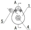
Fig. 1 is the overall structure sketch map of the utility model embodiment;
Fig. 2 be among Fig. 1 A-A to the sectional structure sketch map.
Mark among the figure:
1. remove the glue box; 2. malthoid; 3. push pedal; The silk post; 5. oil nozzle joint.
The specific embodiment
With reference to the accompanying drawings, in conjunction with embodiment, the rip cutting marking press that the utility model is provided remove adhesive dispenser, carry out detailed explanation.
Embodiment
With reference to Fig. 1-Fig. 2, the rip cutting marking press of present embodiment remove adhesive dispenser, be arranged on the two sides of rip cutting marking press cutting knife; It comprises be arranged on the cutting knife both sides remove glue box 1, malthoid 2, push pedal 3, malthoid 2, push pedal 3 are arranged on except that in the glue box 1, remove glue box 1 side and are provided with screwed hole; Malthoid 2 one sides are arranged on the side of cutting knife; Push pedal 3 one sides are the contact plates that are connected with malthoid 2, between wherein are to be provided with threaded silk post 4, cooperate with the screwed hole that removes glue box 1; The said part of holding malthoid 2, push pedal 3 except that glue box 1 is for circular; Said malthoid 2 is cylindrical; Silk post 4 end faces of said push pedal 3 have the elongated slot or six square toes of convenient adjustment silk post 4; Said glue box 1 sidewall that removes is provided with oil nozzle joint 5.
Claims (5)
- A rip cutting marking press remove adhesive dispenser, be arranged on the two sides of rip cutting marking press cutting knife, it is characterized in that: it comprise be arranged on the cutting knife both sides remove glue box, malthoid, push pedal; Malthoid, push pedal are arranged on except that in the glue box; Remove glue box side and be provided with screwed hole, malthoid one side is arranged on the side of cutting knife, and push pedal one side is the contact plate that is connected with malthoid; Be to be provided with threaded silk post wherein, cooperate with the screwed hole that removes the glue box.
- 2. rip cutting marking press according to claim 1 remove adhesive dispenser, it is characterized in that: saidly remove part that the glue box holds malthoid, push pedal for circular.
- 3. rip cutting marking press according to claim 1 remove adhesive dispenser, it is characterized in that: said malthoid is cylindrical.
- 4. rip cutting marking press according to claim 1 remove adhesive dispenser, it is characterized in that: the silk styletable face of said push pedal has the elongated slot or six square toes of convenient adjustment silk post.
- 5. rip cutting marking press according to claim 1 remove adhesive dispenser, it is characterized in that: the said glue box sidewall that removes is provided with the oil nozzle joint.
Priority Applications (1)
| Application Number | Priority Date | Filing Date | Title |
|---|---|---|---|
| CN2011205647382U CN202491476U (en) | 2011-12-30 | 2011-12-30 | Adhesive removal device of longitudinally-cutting indentation machine |
Applications Claiming Priority (1)
| Application Number | Priority Date | Filing Date | Title |
|---|---|---|---|
| CN2011205647382U CN202491476U (en) | 2011-12-30 | 2011-12-30 | Adhesive removal device of longitudinally-cutting indentation machine |
Publications (1)
| Publication Number | Publication Date |
|---|---|
| CN202491476U true CN202491476U (en) | 2012-10-17 |
Family
ID=46997715
Family Applications (1)
| Application Number | Title | Priority Date | Filing Date |
|---|---|---|---|
| CN2011205647382U Expired - Fee Related CN202491476U (en) | 2011-12-30 | 2011-12-30 | Adhesive removal device of longitudinally-cutting indentation machine |
Country Status (1)
| Country | Link |
|---|---|
| CN (1) | CN202491476U (en) |
Cited By (1)
| Publication number | Priority date | Publication date | Assignee | Title |
|---|---|---|---|---|
| CN103522603A (en) * | 2013-11-05 | 2014-01-22 | 宁夏新航能源环境科技有限公司 | Energy-saving marking press |
-
2011
- 2011-12-30 CN CN2011205647382U patent/CN202491476U/en not_active Expired - Fee Related
Cited By (1)
| Publication number | Priority date | Publication date | Assignee | Title |
|---|---|---|---|---|
| CN103522603A (en) * | 2013-11-05 | 2014-01-22 | 宁夏新航能源环境科技有限公司 | Energy-saving marking press |
Similar Documents
| Publication | Publication Date | Title |
|---|---|---|
| CN202491476U (en) | Adhesive removal device of longitudinally-cutting indentation machine | |
| CN203998246U (en) | Damping winding shaft structure for guIllotine | |
| CN103072156A (en) | Adjustable die plate structure of flat die-cutting machine | |
| CN103737974A (en) | Corrugated board pre-pressed line device | |
| CN204339855U (en) | A kind of partition-type hobboing cutter | |
| CN202778123U (en) | Dried paper powder absorbing device | |
| CN203197982U (en) | Manual cutting machine | |
| CN203579773U (en) | Punching mechanism of honeycomb paper core | |
| CN203112697U (en) | Adjustable gluing station | |
| CN201808156U (en) | Cutting table | |
| CN201026627Y (en) | Be applied to quick elevating system of swager roll of slitting, cutter | |
| CN203844291U (en) | Dual-cutting-edge mark pressing knife on honeycomb paperboard marking press | |
| CN202054477U (en) | Dividing and cutting device with straight cutters | |
| CN203857256U (en) | Sectional material and plate connection fixing device | |
| CN202491260U (en) | Cutter anvil device of longitudinally-cutting indentation machine | |
| CN204382358U (en) | A kind of slitter hand papercutter backing plate | |
| CN204673687U (en) | Singe screw multi-control standard splitting machine rack structure | |
| CN215881805U (en) | Drench membrane cardboard fishplate bar orthotic devices | |
| CN202910923U (en) | Sheet type cutter anvil for corrugated board slitting machine | |
| CN203845514U (en) | Bobbin-paper fixing device of splitting machine | |
| CN205553347U (en) | Corrugated container board guillootine | |
| CN203143783U (en) | Square-bag feeding device with cutters capable of being rapidly adjusted | |
| CN210238155U (en) | Tail paper sheet pre-breaking device applied to high-density fiberboard former | |
| CN205043982U (en) | A large stone cutting machine rotary table bottom plate | |
| CN203199775U (en) | Paper cutting device |
Legal Events
| Date | Code | Title | Description |
|---|---|---|---|
| C14 | Grant of patent or utility model | ||
| GR01 | Patent grant | ||
| CF01 | Termination of patent right due to non-payment of annual fee |
Granted publication date: 20121017 Termination date: 20181230 |
|
| CF01 | Termination of patent right due to non-payment of annual fee |