CN202491467U - Deviation rectification base device for longitudinally-cutting indentation machine groups - Google Patents
Deviation rectification base device for longitudinally-cutting indentation machine groups Download PDFInfo
- Publication number
- CN202491467U CN202491467U CN2011205647467U CN201120564746U CN202491467U CN 202491467 U CN202491467 U CN 202491467U CN 2011205647467 U CN2011205647467 U CN 2011205647467U CN 201120564746 U CN201120564746 U CN 201120564746U CN 202491467 U CN202491467 U CN 202491467U
- Authority
- CN
- China
- Prior art keywords
- heat retaining
- board
- base device
- concavo
- bedframe
- Prior art date
- Legal status (The legal status is an assumption and is not a legal conclusion. Google has not performed a legal analysis and makes no representation as to the accuracy of the status listed.)
- Expired - Fee Related
Links
- 238000007373 indentation Methods 0.000 title 1
- 230000005484 gravity Effects 0.000 claims description 3
- 239000011162 core material Substances 0.000 abstract 3
- VYPSYNLAJGMNEJ-UHFFFAOYSA-N Silicium dioxide Chemical compound O=[Si]=O VYPSYNLAJGMNEJ-UHFFFAOYSA-N 0.000 abstract 2
- 239000011888 foil Substances 0.000 abstract 2
- 239000000463 material Substances 0.000 abstract 2
- 239000000203 mixture Substances 0.000 abstract 2
- 239000004570 mortar (masonry) Substances 0.000 abstract 2
- 229920005830 Polyurethane Foam Polymers 0.000 abstract 1
- 239000004964 aerogel Substances 0.000 abstract 1
- 239000010883 coal ash Substances 0.000 abstract 1
- 239000003063 flame retardant Substances 0.000 abstract 1
- 239000003365 glass fiber Substances 0.000 abstract 1
- 239000011325 microbead Substances 0.000 abstract 1
- 239000002245 particle Substances 0.000 abstract 1
- 229910001562 pearlite Inorganic materials 0.000 abstract 1
- 229920006327 polystyrene foam Polymers 0.000 abstract 1
- 239000011496 polyurethane foam Substances 0.000 abstract 1
- 235000012239 silicon dioxide Nutrition 0.000 abstract 1
- 239000000377 silicon dioxide Substances 0.000 abstract 1
- 230000009286 beneficial effect Effects 0.000 description 1
- 239000007858 starting material Substances 0.000 description 1
- 230000001360 synchronised effect Effects 0.000 description 1
Images

Landscapes
- Details Of Cutting Devices (AREA)
Abstract
A concavo-convex vacuum heat retaining board is mainly composed of a heat retaining core material board and an alumium-foil vacuum thermal insulating bag, wherein inorganic heat retaining materials (such as pearlite particles, vitrified micro-beads, coal ash, powdery silicon dioxide, aerogel, ultra-thin glass fibers and the like) or organic heat retaining materials (such as open-cell polyurethane foam, open-cell polystyrene foam and the like) are evenly mixed together through a mixer, and then dried; besides, a getter is added to the mixture; the mixture is pressed into the heat retaining core material board with the concavo-convex surface structure by means of a special mold; and finally, the formed heat retaining core material board is placed into the high fire retardant alumium-foil vacuum thermal insulating bag, and then sealed by extracting air in the bag by means of a vacuum unit. Compared with the prior art, as the concavo-convex vacuum heat retaining board is provided with the concavo-convex surface structure, the bonding force of the heat retaining board with bonding mortar can be enhanced and the reduction of the bonding force caused by the preparation factor of the bonding mortar can be made up; and the capability of the heat retaining board resisting hollowing and drop under the action of external force can be improved.
Description
Technical field
The utility model belongs to the base of corrugated board rip cutting marking press, is specifically related to a kind of rip cutting marking press unit base device.
Background technology
The existing rip cutting marking press unit deviation correcting device of producing corrugated board is direct correction to whole unit, and for the rip cutting marking press of multicomputer combination, each unit has independently deviation correction mechanism, is difficult to keep correction synchronous; Perhaps deviation correction mechanism is fixed on the unit, and all the other units are fastenedly connected with it, forms a cantilever, realizes integral error correcting and position, and is dexterous inadequately.
Summary of the invention
In order to overcome the problems referred to above that the prior art field exists; The purpose of the utility model is; A kind of rip cutting impression unit correction base device is provided, and unit is fixed on its base, realizes unit and base integral error correcting and position; For the rip cutting marking press of multicomputer combination, nonsynchronous problem of avoiding rectifying a deviation.
The rip cutting impression unit correction base device that the utility model provides; Bedframe, supporting seat that said correction base device comprises drive unit, is made up of beam in length and breadth; Supporting seat, drive unit are fixedly installed on the mounting platform; The output of drive unit is connected with bedframe, and bedframe is provided with the translation roller for four jiaos, cooperates with roller supporting surface on being fixed on supporting seat; Said drive unit comprises motor, leading screw, screw, and motor is fixedly installed on the mounting platform, and its output shaft connects leading screw, and leading screw cooperates with screw, and screw is fixedly connected with the longeron of bedframe; It also comprises guide roller, and the fixed support of guide roller is arranged on the bedframe, cooperates with guide roller support on being fixed on supporting seat; Said guide roller is arranged on the position of centre of gravity of unit.
The rip cutting impression unit correction base device that the utility model provides, its beneficial effect is that realization base and a plurality of units that are fixed on the base thereof are rectified a deviation more convenient dexterity simultaneously.
Description of drawings
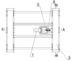
Fig. 1 is the overall structure sketch map of the utility model embodiment;
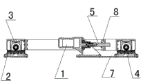
Fig. 2 be among Fig. 1 A-A to the sectional structure sketch map;
Fig. 3 be among Fig. 1 B-B to the sectional structure sketch map.
Mark among the figure:
1. motor; 2. supporting seat; 3. bedframe; 4. guide roller; 5. leading screw; 6. translation roller; 7. mounting platform; 8 screws.
The specific embodiment
With reference to the accompanying drawings, in conjunction with embodiment, the rip cutting impression unit correction base device to the utility model provides carries out detailed explanation.
Embodiment
With reference to Fig. 1-Fig. 3; The rip cutting impression unit correction base device of present embodiment; Said correction base comprises drive unit, by bedframe 3, supporting seat 2 that beam is in length and breadth formed, supporting seat 2, drive unit are fixedly installed on the mounting platform 7, the output of drive unit is connected with bedframe 3; Bedframe is provided with translation roller 6 for 3 four jiaos, cooperates with roller supporting surface on being fixed on supporting seat 2; Said drive unit comprises motor 1, leading screw 5, screw 8, and motor 1 is fixedly installed on the mounting platform 7, and its output shaft connects leading screw 5, and leading screw 5 cooperates with screw 8, and screw 8 is fixedly connected with the longeron of bedframe 3; It also comprises guide roller 4, and the fixed support of guide roller 4 is arranged on the bedframe 3, cooperates with guide roller support on being fixed on supporting seat 2; Said guide roller 4 is arranged on the position of centre of gravity of unit.
When appearance in the transportation that cardboard is advancing is crooked; Starter motor 1, guide roller 4 drives leading screw 5 and makes bedframe 3 move left and right, and tangent line marking press unit moves; Cardboard is motionless; Until the optimum state of adjusting to cardboard, realization base and a plurality of units that are fixed on the base thereof are rectified a deviation more convenient dexterity simultaneously.
Claims (4)
1. rip cutting impression unit correction base device; It is characterized in that: bedframe, supporting seat that said correction base device comprises drive unit, is made up of beam in length and breadth; Supporting seat, drive unit are fixedly installed on the mounting platform; The output of drive unit is connected with bedframe, and bedframe is provided with the translation roller for four jiaos, cooperates with roller supporting surface on being fixed on supporting seat.
2. rip cutting impression unit correction base device according to claim 1; It is characterized in that: said drive unit comprises motor, leading screw, screw, and motor is fixedly installed on the mounting platform, and its output shaft connects leading screw; Leading screw cooperates with screw, and screw is fixedly connected with the longeron of bedframe.
3. rip cutting impression unit according to claim 1 correction base device, it is characterized in that: it also comprises guide roller, the fixed support of guide roller is arranged on the bedframe, cooperates with guide roller support on being fixed on supporting seat.
4. rip cutting impression unit correction base device according to claim 3, it is characterized in that: said guide roller is arranged on the position of centre of gravity of unit.
Priority Applications (1)
| Application Number | Priority Date | Filing Date | Title |
|---|---|---|---|
| CN2011205647467U CN202491467U (en) | 2011-12-30 | 2011-12-30 | Deviation rectification base device for longitudinally-cutting indentation machine groups |
Applications Claiming Priority (1)
| Application Number | Priority Date | Filing Date | Title |
|---|---|---|---|
| CN2011205647467U CN202491467U (en) | 2011-12-30 | 2011-12-30 | Deviation rectification base device for longitudinally-cutting indentation machine groups |
Publications (1)
| Publication Number | Publication Date |
|---|---|
| CN202491467U true CN202491467U (en) | 2012-10-17 |
Family
ID=46997706
Family Applications (1)
| Application Number | Title | Priority Date | Filing Date |
|---|---|---|---|
| CN2011205647467U Expired - Fee Related CN202491467U (en) | 2011-12-30 | 2011-12-30 | Deviation rectification base device for longitudinally-cutting indentation machine groups |
Country Status (1)
| Country | Link |
|---|---|
| CN (1) | CN202491467U (en) |
-
2011
- 2011-12-30 CN CN2011205647467U patent/CN202491467U/en not_active Expired - Fee Related
Similar Documents
| Publication | Publication Date | Title |
|---|---|---|
| CN202491467U (en) | Deviation rectification base device for longitudinally-cutting indentation machine groups | |
| CN202000507U (en) | Aluminum foil air layer compounded heat-insulating plate | |
| CN104890297A (en) | Automatic heat-sealing device used for dialysis paper heat-sealing and cutting equipment | |
| CN114789514A (en) | An integrated saw chain cutting system and installation method of a modular saw blade unit | |
| CN103921341A (en) | Cutting and workpiece pushing linkage device for foaming cement thermal insulation board | |
| CN205892105U (en) | Brick device is got to brickmaking machine | |
| CN205530741U (en) | Composite insulation board | |
| CN207193120U (en) | Based on the diced system that fixation is adsorbed when being repaired to electric instrument dish cart surface glass | |
| CN203158896U (en) | Sheet placing platform | |
| CN206396961U (en) | A kind of lightweight curtain wall panel | |
| CN213226384U (en) | Online transverse cutting device for phenolic aldehyde plate | |
| CN203092734U (en) | Portable type building block cutting machine | |
| CN209887906U (en) | Multi-sheet continuous stone cutting machine | |
| CN203595352U (en) | Stone surface cleaning device | |
| CN215281463U (en) | Sheet taking device used after grinding of glass panel | |
| CN203568483U (en) | Guiding device used for transportation of glass | |
| CN202400466U (en) | an inner packing box | |
| CN201991186U (en) | A heat insulating brick with supporting feet | |
| CN219311377U (en) | An auxiliary positioning device for production and cutting of polyurethane insulation board | |
| CN204094964U (en) | A kind of cutting machine for foam cement partition plate | |
| CN2321861Y (en) | Active floor | |
| CN208087020U (en) | Elevator heat insulation structural | |
| CN203008220U (en) | Double-layer thermal-insulation color steel plate | |
| CN215203830U (en) | Lightweight environment-friendly sandwich composite sheet | |
| CN104373768A (en) | Vacuum insulation plate flatness improving device and method |
Legal Events
| Date | Code | Title | Description |
|---|---|---|---|
| C14 | Grant of patent or utility model | ||
| GR01 | Patent grant | ||
| CF01 | Termination of patent right due to non-payment of annual fee |
Granted publication date: 20121017 Termination date: 20191230 |
|
| CF01 | Termination of patent right due to non-payment of annual fee |