CN202491235U - Multifunctional storage device of tool - Google Patents
Multifunctional storage device of tool Download PDFInfo
- Publication number
- CN202491235U CN202491235U CN2011205465806U CN201120546580U CN202491235U CN 202491235 U CN202491235 U CN 202491235U CN 2011205465806 U CN2011205465806 U CN 2011205465806U CN 201120546580 U CN201120546580 U CN 201120546580U CN 202491235 U CN202491235 U CN 202491235U
- Authority
- CN
- China
- Prior art keywords
- loam cake
- storage device
- groove
- device body
- tool storage
- Prior art date
- Legal status (The legal status is an assumption and is not a legal conclusion. Google has not performed a legal analysis and makes no representation as to the accuracy of the status listed.)
- Expired - Fee Related
Links
- 238000009434 installation Methods 0.000 claims description 12
- 230000001105 regulatory effect Effects 0.000 claims description 7
- 210000003141 lower extremity Anatomy 0.000 claims description 3
- 238000004080 punching Methods 0.000 claims description 3
- 230000006870 function Effects 0.000 abstract description 4
- 238000012423 maintenance Methods 0.000 description 2
- 230000009286 beneficial effect Effects 0.000 description 1
- 238000005516 engineering process Methods 0.000 description 1
- 230000006386 memory function Effects 0.000 description 1
- 238000012986 modification Methods 0.000 description 1
- 230000004048 modification Effects 0.000 description 1
- 238000000465 moulding Methods 0.000 description 1
Images


Landscapes
- Table Equipment (AREA)
Abstract
The utility model discloses a multifunction storage device of tools. The multifunction storage device of the tools includes a device body and an upper cover. The upper cover is provided with a plurality of bosses. The device body is provided with a plurality of grooves corresponding to the bosses. The upper cover can be arranged at different heights by adjusting different positions of the bosses in the grooves. Thus, the multifunction storage device of tools can be used as a table or a stool. At the same time, a plurality of separating boards are arranged in the device body and divides the device body into a plurality of storage spaces. The multifunction storage device of the tools provided by the utility model can be used as a tool storing device. The separating board arranged in the device body facilitates the classified storage of items. At the same time, the multifunction storage device of the tools also can be used as a table or a stool by adjusting the height of the upper cover, thereby increasing functions and broadening the use range. And the multifunction storage device of the tools has an attractive design and a nice appearance.
Description
Technical field
The utility model relates to a kind of multi-purpose tool storage device.
Background technology
In various vehicle maintenance shop such as automobile, bicycle or other any life or electric type maintenance store etc. often to use tool storage device; Tool storage device in the market is fairly simple basically; Only simple placement, the memory function of tool can't provide other as can be used as the function that desk or stool use, and be simple; Performance is single, can not satisfy the needs in market.
The utility model content
The purpose of the utility model is in order to solve the problem of above-mentioned existence, a kind of multi-purpose tool storage device to be provided, comprising device body and loam cake; Said loam cake is provided with some projections; Said device body correspondence is provided with some grooves, can make said loam cake be in different height through regulating said projection at the diverse location of said groove, makes this device can be used as desk or stool use respectively; Be provided with some dividing plates in the said device body simultaneously, be divided into a plurality of memory spaces.It can be used as tool storage device and uses, and the dividing plate of its setting is convenient to article are carried out classification and storage, can be used as desk or stool use again through the height of regulating its loam cake simultaneously, has widened its function and the scope of application, and fashionable attractive in appearance.
The technical scheme of the utility model is following:
A kind of multi-purpose tool storage device comprises device body and loam cake, and said loam cake is provided with some projections, and said device body correspondence is provided with some grooves, can make said loam cake be in different height through regulating said projection at the diverse location of said groove.
Preferably, said projection is located on the medial surface of said loam cake, and said groove is located on the lateral surface of said device body.
Preferably, said loam cake can be in two kinds of different height.
Preferably, said groove is L shaped.
Preferably, the long limit groove of said L shaped groove and the parallel axes of said device body.
Preferably, the long limit groove of said L shaped groove and minor face groove junction are provided with boss, and the minor face groove that it can be fixed on the projection of said loam cake said L shaped groove makes its unlikely said long limit groove that slips into cause said loam cake landing.
Preferably, the minor face groove of said L shaped groove is provided with the installation slotted eye that passes to said device body top edge, makes said loam cake snap in or to take out through said installation slotted eye.
Preferably, said installation slotted eye is located at the minor face groove end of said L shaped groove.
Preferably, said some projections can make its inside perk form through the sub-fraction along the said loam cake lower limb of axis direction punching press of vertical said loam cake.
Preferably, be provided with some dividing plates in the said device body, be divided into a plurality of memory spaces.
Compared with prior art, the beneficial effect of the utility model is following:
The utility model can be used as tool storage device and uses, and the dividing plate of its setting is convenient to article are carried out classification and storage, can be used as desk or stool use again through the height of regulating its loam cake simultaneously, has widened its function and the scope of application, and fashionable attractive in appearance.
Description of drawings
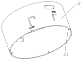
Fig. 1 is the sketch map of the utility model embodiment loam cake;
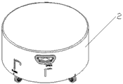
Fig. 2 is the sketch map of the utility model embodiment device body;
Fig. 3 is the scheme of installation of the utility model embodiment;
Fig. 4 is the sketch map of the higher height and position of the utility model embodiment;
Fig. 5 is the sketch map of the lower height and position of the utility model embodiment.
The specific embodiment
A kind of multi-purpose tool storage device comprises device body and loam cake, and said loam cake is provided with some projections, and said device body correspondence is provided with some grooves, can make said loam cake be in different height through regulating said projection at the diverse location of said groove.
Below in conjunction with accompanying drawing and specific embodiment the utility model is done further description.
Embodiment
A kind of multi-purpose tool storage device comprises device body 1 and loam cake 2, and loam cake 2 is provided with some projections, and device body 1 correspondence is provided with some grooves, can make loam cake 2 be in different height through regulating said projection at the diverse location of said groove.Loam cake 2 can be in two kinds of different height in the present embodiment, is referred to as higher height and position and lower height and position respectively.
In the present embodiment, loam cake 2 is provided with four projections, and device body 1 correspondence is provided with four grooves, and said projection is located on the medial surface of loam cake 2, and said groove is located on the lateral surface of device body 1, sees Fig. 1 and Fig. 2 for details.Projection described in the present embodiment is through the sub-fraction along axis direction punching press loam cake 2 lower limbs of vertical loam cake 2 its inside perk to be formed.Be merely for example, during practical implementation, the quantity of the groove of the quantity of the projection of loam cake setting and device body setting and the molding mode of projection also can have a lot of distortion here, and the utility model does not limit this.
In the present embodiment, said groove is L shaped, and the long limit groove of said L shaped groove and the parallel axes of said device body.Be merely for example, during practical implementation, the shape of the groove of device body setting also can have a lot of distortion here, and the utility model does not limit this.
In the present embodiment, the long limit groove of said L shaped groove and minor face groove junction also are provided with boss, and said boss can be fixed on the projection of loam cake 2 the minor face groove of said L shaped groove, make its unlikely said long limit groove that slips into cause loam cake 2 landings.
In the present embodiment, the minor face groove end of said L shaped groove is provided with the installation slotted eye that passes to device body 1 top edge, makes loam cake 2 snap in or to take out through said installation slotted eye.Be merely for example, during practical implementation, also can there be a lot of distortion the position of the installation slotted eye of device body setting here, and the utility model does not limit this.
In the present embodiment, the lower end of device body 1 also is provided with universal wheel and makes it easy to move, and while loam cake 2 is provided with handle and is convenient to grasping and dismounting.Be merely for example, during practical implementation, device body and loam cake also can be provided with other assembly, also can not comprise said modules here, and the utility model does not limit this.
In the present embodiment, be provided with some dividing plates in the device body 1, be divided into a plurality of memory spaces, the dividing plate number that here is provided with is 4, referring to Fig. 2.Be merely for example, during practical implementation, the quantity of the dividing plate of device body setting also can have a lot of distortion here, and the utility model does not limit this.
Because the said projection that is positioned at loam cake 2 is identical with the structure and the occupation mode of the said slotted eye that is positioned at device body 1, will combine below accompanying drawing with wherein one group be that example describes.
Referring to Fig. 1, Fig. 2 and Fig. 3, the L shaped groove 11 on the projection 21 corresponding intrument bodies 1 on the loam cake 2, wherein L shaped groove 11 comprise long limit groove 111, minor face groove 112, boss 113 and slotted eye 114 are installed, referring to Fig. 2.During installation; Projection on the loam cake 2 21 is aimed at installation slotted eye 114 put into, clockwise direction rotation afterwards makes projection 21 snap in minor face groove 112, and this moment, loam cake 2 was in higher height and position; Like Fig. 3, this moment, said multi-purpose tool storage device also can be used as the desk use; If need make said multi-purpose tool storage device be in lower height and position; Only need upwards to mention slightly loam cake 2; The boss 113 that clockwise direction rotation afterwards makes the projection 21 of loam cake 2 cross the L shaped groove 11 of device body 1 gets into the long limit groove 111 of L shaped groove 11 and to transferring to bottom land; Can make the multi-purpose tool storage device be in lower height and position, like Fig. 4, this moment, the multi-purpose tool storage device also can be used as the stool use.
The utility model preferred embodiment disclosed herein just is used for helping to set forth the utility model.Preferred embodiment does not have all details of detailed descriptionthe, does not limit this utility model yet and is merely the described specific embodiment.Obviously, according to the content of this specification, can do a lot of modifications and variation.These embodiment are chosen and specifically described to this specification, is principle and practical application in order to explain the utility model better, thereby make one of ordinary skill in the art can utilize the utility model well.The utility model only receives the restriction of claims and four corner and equivalent.
Claims (10)
1. multi-purpose tool storage device; Comprise device body and loam cake, it is characterized in that said loam cake is provided with some projections; Said device body correspondence is provided with some grooves, can make said loam cake be in different height through regulating said projection at the diverse location of said groove.
2. according to the said multi-purpose tool storage device of claim 1, it is characterized in that said projection is located on the medial surface of said loam cake, said groove is located on the lateral surface of said device body.
3. according to the said multi-purpose tool storage device of claim 1, it is characterized in that said loam cake can be in two kinds of different height.
4. according to claim 1 or 2 or 3 said multi-purpose tool storage devices, it is characterized in that said groove is L shaped.
5. according to the said multi-purpose tool storage device of claim 4, it is characterized in that the long limit groove of said L shaped groove and the parallel axes of said device body.
6. according to the said multi-purpose tool storage device of claim 4; It is characterized in that; The long limit groove of said L shaped groove and minor face groove junction are provided with boss, and the minor face groove that it can be fixed on the projection of said loam cake said L shaped groove makes its unlikely said long limit groove that slips into cause said loam cake landing.
7. according to the said multi-purpose tool storage device of claim 4, it is characterized in that the minor face groove of said L shaped groove is provided with the installation slotted eye that passes to said device body top edge, make said loam cake snap in or to take out through said installation slotted eye.
8. according to the said multi-purpose tool storage device of claim 7, it is characterized in that said installation slotted eye is located at the minor face groove end of said L shaped groove.
9. according to claim 1 or 2 said multi-purpose tool storage devices, it is characterized in that said some projections can make its inside perk form through the sub-fraction along the said loam cake lower limb of axis direction punching press of vertical said loam cake.
10. according to the said multi-purpose tool storage device of claim 1, it is characterized in that, be provided with some dividing plates in the said device body, be divided into a plurality of memory spaces.
Priority Applications (1)
| Application Number | Priority Date | Filing Date | Title |
|---|---|---|---|
| CN2011205465806U CN202491235U (en) | 2011-12-23 | 2011-12-23 | Multifunctional storage device of tool |
Applications Claiming Priority (1)
| Application Number | Priority Date | Filing Date | Title |
|---|---|---|---|
| CN2011205465806U CN202491235U (en) | 2011-12-23 | 2011-12-23 | Multifunctional storage device of tool |
Publications (1)
| Publication Number | Publication Date |
|---|---|
| CN202491235U true CN202491235U (en) | 2012-10-17 |
Family
ID=46997475
Family Applications (1)
| Application Number | Title | Priority Date | Filing Date |
|---|---|---|---|
| CN2011205465806U Expired - Fee Related CN202491235U (en) | 2011-12-23 | 2011-12-23 | Multifunctional storage device of tool |
Country Status (1)
| Country | Link |
|---|---|
| CN (1) | CN202491235U (en) |
-
2011
- 2011-12-23 CN CN2011205465806U patent/CN202491235U/en not_active Expired - Fee Related
Similar Documents
| Publication | Publication Date | Title |
|---|---|---|
| CN202491235U (en) | Multifunctional storage device of tool | |
| CN204845297U (en) | Multi -functional office supplies platform | |
| CN206777054U (en) | A kind of New-type instant formula desk | |
| CN203407656U (en) | Multifunctional writing case | |
| CN201317319Y (en) | Building block type automobile back-up tank storage box | |
| CN203188473U (en) | Partly inward concavity type irregular circular arc box component | |
| CN202024170U (en) | Desk lamp with pen container and name card box | |
| CN201831307U (en) | Multifunctional book stand | |
| CN201641024U (en) | Rotary bookshelf module | |
| CN201900641U (en) | Three-dimensional tool box | |
| CN202892916U (en) | Book end toy | |
| CN205416959U (en) | Art design instrument storage device | |
| CN205125498U (en) | Novel student's bench | |
| CN203369591U (en) | Free-assembly bookshelf | |
| CN204802213U (en) | Packing box | |
| CN203875881U (en) | Multifunctional tool cart | |
| CN202959472U (en) | Bookshelf | |
| CN201646119U (en) | Magnetic drawing board with object storage box | |
| CN205113894U (en) | Novel environmental protection file box | |
| CN203232234U (en) | Large folding photography light complement lamp | |
| CN203386963U (en) | Desktop socket having storage box | |
| CN102774547A (en) | Packing box for cup mat | |
| CN202546456U (en) | Multifunctional desk lamp | |
| CN202572718U (en) | Multi-function composable mold | |
| CN203110672U (en) | Multifunctional column-shaped ruler |
Legal Events
| Date | Code | Title | Description |
|---|---|---|---|
| C14 | Grant of patent or utility model | ||
| GR01 | Patent grant | ||
| C17 | Cessation of patent right | ||
| CF01 | Termination of patent right due to non-payment of annual fee |
Granted publication date: 20121017 Termination date: 20131223 |