Drill lip is stained with sticking device automatically
Technical field
The utility model relates to a kind of sticking wheel that sticking scrap is used of being stained with, particularly a kind of be stained with sticking fine drill lip in grind the back residual scrap use be stained with sticking device automatically.
Background technology
Generally be applied to employed drill bit on the bore operation of printed circuit board (PCB), its drill lip diameter can be small to the 0.1mm, this kind drill bit in the industry cycle is commonly referred to as micro drill.
And have the first sword face and the second sword face on the drill lip of knowledge micro drill, these sword faces normally form via attrition process; Therebetween, be included in and produce micro drill attrition process first at that time, and use a period of time and the regrind processing carried out after the passivation, the scrap that on this sword face, is generated during residual the grinding all easily at micro drill; In the process of Drilling printed circuit board (PCB), the scrap that these remain on the sword face is easy to cause erroneous judgement visually for micro drill, and then causes producing yield decline.
Said circumstances; Particularly adopted automated process mostly at bore operation in the face of printed circuit board (PCB); And very many of the quantity of the micro drill that uses in its processing procedure have a scrap if the sword face on most micro drill is all residual, certainly will influence the yield that produces of printed circuit board (PCB).
Yet, with state of the art, adopt the artificial also manually sticking mode of removing scrap on the sword face of drill lip of inspecting one by one mostly, when having ground the micro drill of completion in the face of majority, showing has the clear problem of debris removal efficient to treat to overcome.
Summary of the invention
The purpose of the utility model aims to provide a kind of drill lip and is stained with sticking device automatically, improves the unclear problem of efficient that tradition is removed residual scrap on the fine drill lip.
The utility model is to be stained with sticking device automatically to the drill lip that micro drill provided after the attrition process, and it can individualism or is disposed at the side of drill lip automatic grinding mechanism.Wherein, this grinding back or residual have the micro drill of scrap must be can continue to be supplied to automatically one wait to be stained with sticking scrap the ad-hoc location location, implement the utility model under the situation that its sword face is appeared.
The technological means of the utility model comprises:
One base station, it is provided with one first driver;
One first slide unit, it is slidedly arranged on this base station, and this first slide unit is provided with one second driver; And
One second slide unit, it is slidedly arranged on this first slide unit, and this second slide unit is provided with a cam and a sticking wheel; This second slide unit is pivoted a rotor to contact this cam, and this this cam of second driver drives makes this second slide unit move back and forth one and is stained with drilling depth; And pass through this cam driven and should stickingly take turns; Make this sticking take turns in this second slide unit move back and forth this be stained with drilling depth after rotation one transposition angle, this sticking wheel comprises a plurality of transposition angles from turning around, this first driver in this sticking wheel after turning around; Drive this first slide unit displacement, one off normal distance, make this second slide unit follow this this off normal distance of first slide unit displacement.
Further implementing, comprising:
This first driver is a motor, drives this this off normal distance of first slide unit displacement through a ball driving screw.
Form a conduit on this cam, this conduit is made up of a plurality of mound portions and a plurality of paddy portion that is surrounded between the portion of said mound, and this rotor is in this conduit and roll between said mound portion and paddy portion.
Should sticking wheel have storage tank filling clay and form the adhesion body of dish-type, this adhesion body has the filling thickness of being stained with drilling depth greater than this, and has and hold a plurality of these off normals apart from the width of summing up.
This second driver is a motor, drives this cam through a belt pulley, makes this cam and should stickingly take turns this transposition angle of synchronous stepping rotation.
This second slide unit is provided with a driving lever, and this driving lever drives in the process that turns around at this cam should sticking this transposition angle of wheel rotation.
The first-class circle spacing of wheel face that should sticking wheel form a plurality of ratchet grooves radially, and this driving lever is to embed in this ratchet groove, and drive should the rotation of sticking wheel should the transposition angle.
This is stained with drilling depth and the off normal distance is different linear axial.
According to above-mentioned technological means, the utility model possesses following usefulness:
1. should sticking take turns in carrying out disposablely when moving back and forth this action of being stained with drilling depth, the body one of will adhere is specific is stained with sticky point implantation drill lip and is stained with drilling depth to this and retreats and leave, and glues and removes the scrap on the drill lip in order to be stained with.
2. should sticking wheel accomplish disposable move back and forth this action of being stained with drilling depth after; Can be stained with rotation one transposition angle on the circumferential path of sticky point in this; So that when secondary is stained with sticking same or different drill lip; The different sticky points of being stained with on can this circumferential path of conversion, and then keep the sticking ability of being stained with that the adhesion body is removed scrap on the drill lip.
3. should the stepping intermittently of sticking wheel implement in a plurality of transposition angle processes; Particularly sticking wheel during turning around, make be close on this circumferential path be covered with different when being stained with sticky point; Action via first this off normal distance of slide unit displacement; Can be converted on the different circumferential path and make this be stained with sticky point, and then one by one the enforcement difference on this different circumferential path that the continues debris removal action of being stained with sticky point, relying to make full use of on the adhesion body can be made for to being stained with the dish-type effective area of sticky point.
Understand above-mentioned technological means of the utility model and usefulness thereof for abundant, and implement the utility model according to this, see also the explanation of embodiment content and conjunction with figs. as follows:
Description of drawings
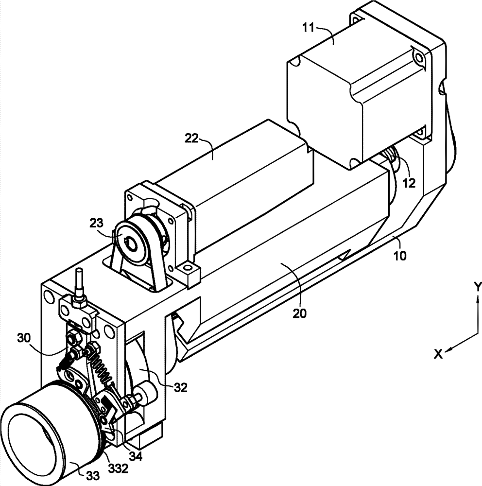
Fig. 1 is the schematic perspective view of the utility model;
Fig. 2 is the cut-away view of Fig. 1;
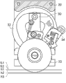
Fig. 3 is the cut-away view of A-A section among Fig. 2;
Fig. 3 a to Fig. 3 e is the different action sketch map of being stained with drilling depth of Fig. 3 cam conversion;
Fig. 4 a is the partial enlarged drawing of sticking wheel among Fig. 2;
Fig. 4 b is the cut-away view of C-C section among Fig. 4 a.
Description of reference numerals: 10-base station; 11-first driver; 12-ball driving screw; 20-first slide unit; The 21-slide rail; 22-second driver; 23-first belt pulley; The 24-rotor; 30-second slide unit; 31-second belt pulley; The 32-cam; The 321-first mound portion; The 322-second mound portion; 323-the 3rd mound portion; The 324-first paddy portion; The 325-second paddy portion; 326-the 3rd paddy portion; The 327-conduit; The 328-protuberance; The sticking wheel of 33-; The 331-body of adhering; 332-ratchet groove; The 34-driving lever; The 41-drill lip; 51,52-is stained with sticky point; H1, h2, h3-are stained with drilling depth; R1, R2, R3, r1, r2, r3-radius distance; α-transposition angle; S-off normal distance; S1-first reference position; S2-second reference position; T-clogs thickness; W-radius width.
The specific embodiment
First see shown in Figure 1ly, explain that the utility model provides a kind of drill lip to be stained with sticking device automatically, be included in one support and the base station 10 of location usefulness on slidingly establish one first slide unit 20, and on this first slide unit 20, slide and establish one second slide unit 30, to implement the assembly of following member:
Definition has different linear axial on this base station 10; This linear axial comprises an X axis and a Y is axial; This base station 10 is provided with one first driver 11, and this first driver 11 can be motor in fact or other can pass the member that object is carried out the running of X axis linear displacement.The end of exerting oneself of this first driver 11 links a ball driving screw 12 (cooperating shown in Figure 2), and the linearity of ordering about these ball driving screw 12 generation X axis moves back and forth.
Be provided with a slide rail 21 (as shown in Figure 2) of X axis between this first slide unit 20 and this base station 10, this first slide unit 20 is slidedly arranged on this base station 10, can move back and forth along the X axis generation.This first driver 11 links these first slide units 20 through this ball driving screw 14, with drive this first slide unit 20 along X axis displacement one off normal apart from S.This first slide unit 20 is provided with one second driver 22, and this second driver 22 can be in fact a motor, and the axle center of this second driver 22 is provided with one first belt pulley 23.
This second slide unit 30 is provided with one second belt pulley 31, a cam 32 and a sticking wheel 33; Wherein:
These cam 32 coaxial being fixedly arranged on this second belt pulley 31, this second belt pulley 31 receives 23 drives of first belt pulley of this second driver 22.Form a conduit 327 on this cam 32, this conduit 327 is made up of a plurality of mound portions and a plurality of paddy portion that is surrounded between the portion of said mound.Said mound portion comprises one first mound portion 321, one second mound portion 322 and one the 3rd mound portion 323, and said paddy portion comprises one first paddy portion 324, one second paddy portion 325 and one the 3rd paddy portion 326; The radius distance R1 of this first mound portion 321 is greater than the radius distance R2 and the R3 of this second mound portion 322 and the 3rd mound portion 323, and the radius distance R2 and the R3 of this second mound portion 322 and the 3rd mound portion 323 are identical; The radius distance r1 of this first paddy portion 324 is greater than the radius distance r2 of this second paddy portion 325, and the radius distance r2 of this second paddy portion 325 is greater than the radius distance r3 of the 3rd paddy portion 326.When this second driver 22 drives these cam 32 time rotationals through this first belt pulley 23 and second belt pulley 31, the rotor 24 in this conduit 327 can roll between said mound portion and paddy portion (as shown in Figure 3).
This second slide unit 30 is pivoted this rotor 24 to contact this cam 32, and thus, when this second driver 22 drives these cam 32 time rotationals through this first belt pulley 23 and second belt pulley 31, this second slide unit 30 will carry out following being stained with and bore action:
(1) when these cam 32 rotations, when making this rotor 24 be rolled into the first mound portion 321 of this cam 32 (as shown in Figure 3), this second slide unit 30 is moved upward to one first reference position S1 (shown in Fig. 3 a) on the Y axle;
(2) when these cam 32 rotations; When making this rotor 24 be rolled into the first paddy portion 324 of this cam 32 (as shown in Figure 3); Because the radius distance r1 of this first paddy portion 324 is maximum, so this second slide unit 30 is moved downward to a most shallow drilling depth h1 (shown in Fig. 3 c) that is stained with on the Y axle;
(3) when these cam 32 rotations; When making this rotor 24 be rolled into the second mound portion 322 of this cam 32 (as shown in Figure 3); Because the radius distance R2 of this second mound portion 322 is less than the radius distance R1 of this first mound portion 321, so this second slide unit 30 is moved upward to one second reference position S2 (shown in Fig. 3 b) on the Y axle;
(4) when these cam 32 rotations; When making this rotor 24 be rolled into the second paddy portion 325 of this cam 32 (as shown in Figure 3); Because the radius distance r2 of this second paddy portion 325 is between the radius distance r3 of the radius distance r1 of this first paddy portion 324 and the 3rd paddy portion 326, so this second slide unit 30 is moved downward to once the dark drilling depth h2 (shown in Fig. 3 d) that is stained with on the Y axle;
(5) when these cam 32 rotations; When making this rotor 24 be rolled into the 3rd mound portion 323 of this cam 32 (as shown in Figure 3); Because the radius distance R3 of the 3rd mound portion 323 is less than the radius distance R1 of this first mound portion 321, so this second slide unit 30 is moved upward to one second reference position S2 (shown in Fig. 3 b) on the Y axle;
(6) when these cam 32 rotations; When making this rotor 24 be rolled into the 3rd paddy portion 326 of this cam 32 (as shown in Figure 3); Because the radius distance r3 of the 3rd paddy portion 326 is less than the radius distance r2 of this second paddy portion 325, so this second slide unit 30 is moved downward to a darkest drilling depth h3 (shown in Fig. 3 e) that is stained with on the Y axle.
So implement, this second slide unit 30 can axially be carried out the different action that moves back and forth of being stained with drilling depth h1, h2, h3 towards Y.This is different is stained with drilling depth h1, h2, h3 and is formed by the said mound portion of linking up mutually and the radius difference between the paddy portion.
Should sticking wheel 33 have storage tank filling clay and form the adhesion body 331 of dish-type, this adhesion body 331 has greater than the filling thickness T of being stained with drilling depth h1, h2, h3 (shown in Fig. 4 b), and has and hold the width W (shown in Fig. 4 a) that a plurality of these off normals are summed up apart from S; This second driver 22 drives these first belt pulleys 23 and second belt pulley 31 drives this cam 32, should sticking wheel 33 and drive through this cam 32, make this sticking wheel 33 in this second slide unit 30 move back and forth this be stained with drilling depth after h3, h2, h1 rotation one transposition angle.Wherein should include a plurality of transposition angle [alpha] from turning around synchronously by sticking wheel 33 and second belt pulley 31.
In fact, the first-class circle spacing of wheel face of this sticking wheel 33 forms a plurality of ratchet grooves 332 (as shown in Figure 1) radially.This second slide unit 30 is provided with a driving lever 34, and this driving lever 34 drives in the process that turns around at this cam 32 should sticking this transposition angle [alpha] of wheel 33 rotations.Furthermore, form a protuberance 328 (as shown in Figure 3) on this cam 32, to drive this driving lever 34.When this second slide unit 30 axially carry out towards Y different be stained with drilling depth h1, h2, h3 move back and forth action after; This cam 32 from then make this protuberance 328 drive these driving levers 34; This driving lever 34 then is in this ratchet groove 332 of embedding, should 33 rotations of sticking wheel be somebody's turn to do the transposition angle [alpha] and drive.
This first driver 11 after turning around, drives this this off normal of first slide unit, 20 displacements apart from S (shown in Fig. 4 b) in this sticking wheel 33, makes this second slide unit 30 follow this this off normal of first slide unit, 20 displacements apart from S.Wherein this to be stained with drilling depth h1, h2, h3 and off normal be different linear axial apart from S.
The utility model is according to the assembly and the interlock mode thereof of above-mentioned member; Can wait that the micro drill of being stained with sticking scrap and being positioned at an ad-hoc location carries out automatic debris removal running to one; The drill lip 41 of this micro drill must be under situation about appearing (shown in Fig. 4 a); Make this sticking wheel 33 be adjacent to this drill lip 41 outer ends; Even the sticking wheel 33 that drives on these second slide units 30 with this second driver 22 moves back and forth this and is stained with drilling depth h1, h2 or h3 (cooperating shown in Figure 2) along Y is axially disposable, make on this adhesion body 331 specific one to be stained with sticky point 51 and to implant these drill lips 41, and glue except that the scrap on this drill lip 41.This mode can be carried out the disposable action that this is stained with drilling depth (for example being h1) that moves back and forth to same drill lip 41, perhaps repeatedly moves back and forth this different action of being stained with drilling depth h1, h2 and h3 simultaneously to same drill lip 41.Subsequently; Make this second driver 22 drive sticking wheel 33 and be stained with on the circumferential path C1 of sticky point 51 an once transposition of the rotation angle [alpha] (cooperating shown in Fig. 4 a) of property at this; So that when secondary is stained with sticking same or different drill lip 41; Can this circumferential path of conversion C1 go up the different sticky points 52 of being stained with, and then keep the sticking ability of being stained with that adhesion body 331 is removed scrap on the drill lip 41.
When this sticking wheel 33 stepping is intermittently implemented in a plurality of transposition angle [alpha] processes; Particularly during sticking wheel 33 turns around certainly; Make to be close on the said circumferential path to be covered with and different be stained with sticky point at 51,52 o'clock, can drive the mechanism design of these first slide units 20 and second slide unit 30 via this first driver 11, and make this sticking off normal of 33 displacements of taking turns apart from S (shown in Fig. 2 and Fig. 4 b); So can this circumferential path C1 that is stained with sticky point 51,52 be converted into C2; And then the different circumferential path of conversion that continues, and enforcement difference one by one is stained with the debris removal action of sticky point, relying to make full use of can be made on this adhesion body 331 to being stained with the dish-type effective area of sticky point.
More than this is merely the preferred embodiment of the utility model, not in order to restriction the utility model, interior any modification of making of all spirit at the utility model and principle, replacement, improvement etc., all should be included in scope that the utility model protects in.