CN202491093U - Clamp for machining explosionproof patterns on base die of glass mold - Google Patents
Clamp for machining explosionproof patterns on base die of glass mold Download PDFInfo
- Publication number
- CN202491093U CN202491093U CN2012201366628U CN201220136662U CN202491093U CN 202491093 U CN202491093 U CN 202491093U CN 2012201366628 U CN2012201366628 U CN 2012201366628U CN 201220136662 U CN201220136662 U CN 201220136662U CN 202491093 U CN202491093 U CN 202491093U
- Authority
- CN
- China
- Prior art keywords
- chuck
- explosion
- fixing seat
- mold
- rotating shaft
- Prior art date
- Legal status (The legal status is an assumption and is not a legal conclusion. Google has not performed a legal analysis and makes no representation as to the accuracy of the status listed.)
- Expired - Lifetime
Links
Images

Classifications
-
- Y—GENERAL TAGGING OF NEW TECHNOLOGICAL DEVELOPMENTS; GENERAL TAGGING OF CROSS-SECTIONAL TECHNOLOGIES SPANNING OVER SEVERAL SECTIONS OF THE IPC; TECHNICAL SUBJECTS COVERED BY FORMER USPC CROSS-REFERENCE ART COLLECTIONS [XRACs] AND DIGESTS
- Y02—TECHNOLOGIES OR APPLICATIONS FOR MITIGATION OR ADAPTATION AGAINST CLIMATE CHANGE
- Y02P—CLIMATE CHANGE MITIGATION TECHNOLOGIES IN THE PRODUCTION OR PROCESSING OF GOODS
- Y02P40/00—Technologies relating to the processing of minerals
- Y02P40/50—Glass production, e.g. reusing waste heat during processing or shaping
- Y02P40/57—Improving the yield, e-g- reduction of reject rates
Landscapes
- Jigs For Machine Tools (AREA)
Abstract
本实用新型公开了一种用于玻璃模具底模防爆纹加工的夹具,属于玻璃模具加工技术领域。一种用于玻璃模具底模防爆纹加工的夹具,包括底座,支架、转轴装置、分度卡盘、卡盘固定座、电机;其中,支架和转轴装置设置在底座上,分度卡盘设置在卡盘固定座上,卡盘固定座与转轴装置相连接,调节转轴装置可使卡盘固定座转动,电机设置在卡盘固定座并与分度卡盘相连接,调节电机可驱动分度卡盘转动。由于本实用新型具备了多种形状的防爆纹的加工能力,适宜采用高速机床控制,极大的提高了玻璃模具底模防爆纹加工效率和加工质量。
The utility model discloses a fixture used for processing explosion-proof patterns on the bottom mold of a glass mold, which belongs to the technical field of glass mold processing. A fixture for processing explosion-proof patterns on the bottom mold of a glass mold, including a base, a bracket, a rotating shaft device, an indexing chuck, a chuck fixing seat, and a motor; wherein, the bracket and the rotating shaft device are arranged on the base, and the indexing chuck is arranged on the base On the chuck fixing seat, the chuck fixing seat is connected with the rotating shaft device, adjusting the rotating shaft device can make the chuck fixing seat rotate, the motor is arranged on the chuck fixing seat and connected with the indexing chuck, adjusting the motor can drive the indexing The chuck turns. Since the utility model has the processing capability of explosion-proof patterns of various shapes, it is suitable for high-speed machine tool control, which greatly improves the processing efficiency and quality of the explosion-proof patterns of the bottom mold of the glass mold.
Description
技术领域 technical field
本实用新型属于玻璃模具加工技术领域,具体涉及一种用于玻璃模具底模防爆纹加工的夹具。 The utility model belongs to the technical field of glass mold processing, in particular to a fixture used for processing explosion-proof patterns on the bottom mold of a glass mold.
背景技术 Background technique
如业界所知,玻璃制品从模具中取出后需经传送带送至指定的位置进行后续处理。由于玻璃制品从模具中取出的温度约为650℃左右,而与玻璃制品接触的传送带温度较低,因此在玻璃制品底部与传送带接触的一瞬间,由于温差的存在极易导致玻璃制品底部应力集中而开裂。为解决这种缺陷,玻璃瓶的底部经常设计一些凸出瓶底部的小点,以减少瓶底部与传送带的接触面积,从降低玻璃瓶的冷却速度,避免瓶底爆裂,业界常称之为防爆纹。 As known in the industry, glass products need to be transported to a designated location by a conveyor belt after being taken out of the mold for subsequent processing. Since the temperature at which the glass product is taken out from the mold is about 650°C, and the temperature of the conveyor belt in contact with the glass product is relatively low, the moment the bottom of the glass product contacts the conveyor belt, the stress concentration at the bottom of the glass product is easily caused by the existence of the temperature difference. And cracking. In order to solve this defect, the bottom of the glass bottle is often designed with some small points protruding from the bottom of the bottle to reduce the contact area between the bottom of the bottle and the conveyor belt, thereby reducing the cooling speed of the glass bottle and avoiding the bottom of the bottle from bursting. It is often called explosion-proof in the industry. pattern.
防爆纹通常根据瓶子的结构、客户的喜好、以及外观的欣赏性设计成月牙形、圆点形、条形等多种不同的形状。附图1给出了一种月牙形的防爆纹示意图。由于防爆纹的精度会直接影响到瓶子摆放的稳定性以及瓶子的使用性能, 因此对于加工时的精度要求较高。这些防爆纹通常需要玻璃模具底模限制成型。防爆纹数量多,而且形状复杂,精度要求较高。传统的防爆纹通常采用精雕机雕刻成型,但是效率较低,精度较差,无法满足量大的需求。为此本实用新型人经过长期的探索,开发出一种用于玻璃模具底模防爆纹加工的夹具,配合相应加工的方法,极大的提高了玻璃模具底模防爆纹加工效率。 The explosion-proof pattern is usually designed into a variety of different shapes such as crescent, dot, and bar according to the structure of the bottle, customer preferences, and appreciation of appearance. Attached Figure 1 shows a schematic diagram of a crescent-shaped explosion-proof pattern. Since the accuracy of the explosion-proof pattern will directly affect the stability of the bottle placement and the performance of the bottle, the precision requirements for processing are relatively high. These blast patterns usually require glass mold bottom molds to restrict the formation. The number of explosion-proof lines is large, and the shape is complex, and the precision requirements are high. Traditional explosion-proof patterns are usually engraved by precision engraving machines, but the efficiency is low and the precision is poor, which cannot meet the needs of large quantities. For this reason, after long-term exploration, the inventor of the present invention has developed a fixture for processing the explosion-proof pattern of the glass mold bottom mold, and with the corresponding processing method, the processing efficiency of the explosion-proof pattern of the glass mold bottom mold has been greatly improved.
发明内容 Contents of the invention
本实用新型的任务在于针对上述现有技术中的不足,提供一种用于玻璃模具底模防爆纹加工的夹具,从而提高玻璃模具底模防爆纹加工效率。 The task of this utility model is to provide a fixture for processing the explosion-proof pattern of the bottom mold of the glass mold in order to improve the processing efficiency of the explosion-proof pattern of the bottom mold of the glass mold.
为了达到上述目的,本实用新型采用的技术方案为:一种用于玻璃模具底模防爆纹加工的夹具,包括底座,支架、转轴装置、分度卡盘、卡盘固定座、电机;其中,支架和转轴装置设置在底座上,分度卡盘设置在卡盘固定座上,卡盘固定座与转轴装置相连接,调节转轴装置可使卡盘固定座转动,电机设置在卡盘固定座并与分度卡盘相连接,调节电机可驱动分度卡盘转动。 In order to achieve the above-mentioned purpose, the technical solution adopted by the utility model is: a fixture for the explosion-proof pattern processing of the bottom mold of the glass mold, including a base, a bracket, a rotating shaft device, an indexing chuck, a chuck fixing seat, and a motor; wherein, The bracket and the rotating shaft device are arranged on the base, the indexing chuck is arranged on the chuck fixing seat, the chuck fixing seat is connected with the rotating shaft device, the chuck fixing seat can be rotated by adjusting the rotating shaft device, the motor is arranged on the chuck fixing seat and Connected with the indexing chuck, the adjusting motor can drive the indexing chuck to rotate. the
上述技术方案中,卡盘固定座相对于夹具底座平面的转动角度范围可以为0~90度。 In the above technical solution, the range of the rotation angle of the chuck fixing seat relative to the plane of the fixture base can be 0-90 degrees.
配合该夹具使用的加工方法,包含以下步骤: The processing method used with the fixture includes the following steps:
A)将待加工的玻璃模具底模固定在本夹具的分度卡盘上,调节本夹具的转轴装置控制卡盘固定座的转动角度,将刀具设置在底模防爆纹待加工位置的上方; A) Fix the bottom mold of the glass mold to be processed on the indexing chuck of the fixture, adjust the rotating shaft device of the fixture to control the rotation angle of the chuck fixing seat, and set the tool above the position where the explosion-proof pattern of the bottom mold is to be processed;
B)刀具向底模运动,控制刀具的运动轨迹和速度,在底模上加工出1个防爆纹,然后刀具复位,回到该防爆纹上方; B) The tool moves to the bottom mold, controls the movement trajectory and speed of the tool, and processes an explosion-proof pattern on the bottom mold, then resets the tool and returns to the top of the explosion-proof pattern;
C)控制底模夹具的电机使分度卡盘连同底模一齐转动,使下一个待加工位置转动至刀具下方; C) Control the motor of the bottom mold fixture to make the indexing chuck rotate together with the bottom mold, so that the next position to be processed is rotated to the bottom of the tool;
D)重复B、C步骤,直至将底模上的所有防爆纹加工完毕。 D) Repeat steps B and C until all the explosion-proof patterns on the bottom mold are processed.
本实用新型的有益效果为:由于本实用新型的用于玻璃模具底模防爆纹加工的夹具,其卡盘固定座可以以转轴装置为轴转动、分度卡盘也可以在卡盘固定座的平面内进行转动,再加上刀具可以在垂直空间内运动,因此采用本夹具便可以在3个方向内进行底模防爆纹的加工。根据卡盘固定座转动的角度不同,加工出的防爆纹形状、大小、深度均不同,从而使本夹具具备了多种形状的防爆纹的加工能力。本夹具特别适宜采用高速机床控制,极大的提高了玻璃模具底模防爆纹加工效率和加工质量。 The beneficial effects of the utility model are: due to the fixture used for the explosion-proof pattern processing of the bottom mold of the glass mold of the utility model, the chuck fixing seat can be rotated with the rotating shaft device as the axis, and the indexing chuck can also be mounted on the chuck fixing seat. Rotation in the plane, and the tool can move in the vertical space, so the explosion-proof pattern of the bottom mold can be processed in 3 directions by using this fixture. According to the different rotation angles of the chuck fixing seat, the shape, size and depth of the processed anti-explosion lines are all different, so that the fixture has the ability to process anti-explosion lines of various shapes. This fixture is especially suitable for high-speed machine tool control, which greatly improves the processing efficiency and processing quality of the explosion-proof pattern on the bottom mold of the glass mold.
附图说明 Description of drawings
图1是一种月牙形的玻璃模具防爆纹的示意图。 Figure 1 is a schematic diagram of a crescent-shaped glass mold explosion-proof pattern.
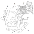
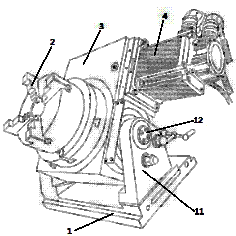
图2是本用于玻璃模具底模防爆纹加工的夹具的结构图,其中1为底座,2为分度卡盘,3为卡盘固定座,4为电机,11为支架,12为转轴装置。 Figure 2 is a structural diagram of the fixture used for processing the explosion-proof pattern of the bottom mold of the glass mold, in which 1 is the base, 2 is the indexing chuck, 3 is the chuck fixing seat, 4 is the motor, 11 is the bracket, and 12 is the rotating shaft device .
具体实施方式 Detailed ways
以下结合具体实施例对本实用新型作进一步详细描述。 Below in conjunction with specific embodiment the utility model is described in further detail.
本实施例中,用于玻璃模具底模防爆纹加工的夹具包括底座1,支架1、转轴装置12、分度卡盘2、卡盘固定座3、电机4;其中,支架11和转轴装置12设置在底座1上,分度卡盘2设置在卡盘固定座3上,卡盘固定座3与转轴装置12相连接,调节转轴装置12可使卡盘固定座3转动,电机4设置在卡盘固定座3并与分度卡盘2相连接,调节电机4可驱动分度卡盘2转动。卡盘固定座3相对于夹具底座平面的转动角度范围可以为0~90度。
In this embodiment, the fixture used for processing the explosion-proof pattern of the glass mold bottom mold includes a
本实施例中,采用本夹具制作玻璃模具底模防爆纹的具体步骤按以下进行: In this embodiment, the specific steps of using this fixture to make the explosion-proof pattern of the bottom mold of the glass mold are as follows:
首先,将待加工的玻璃模具底模固定在本夹具的分度卡盘2上,调节本夹具的转轴装置12控制卡盘固定座3的转动角度,将刀具设置在底模防爆纹待加工位置的上方。刀具的外形根据待加工的防爆纹形状进行选择,与该待加工的防爆纹形状相匹配。
Firstly, fix the bottom mold of the glass mold to be processed on the indexing
然后,刀具向底模运动,控制刀具的运动轨迹和速度,在底模上加工出1个防爆纹,然后刀具复位,回到该防爆纹上方。本实施例中通过机床控制刀具的运动轨迹和速度,机床为精密数控铣床。机床生产厂家为南京信云数控,型号为V40。 Then, the tool moves to the bottom mold, controls the movement trajectory and speed of the tool, and processes an explosion-proof pattern on the bottom mold, and then resets the tool to return to the top of the explosion-proof pattern. In this embodiment, the trajectory and speed of the tool are controlled by a machine tool, which is a precision numerical control milling machine. The machine tool manufacturer is Nanjing Xinyun CNC, and the model is V40.
接着,控制本夹具的电机4使分度卡盘2连同底模一齐转动,使下一个待加工位置转动至刀具下方。分度卡盘2和底模转动速度根据防爆纹的数量和加工时间决定。由于本实施例中底模上防爆纹加工时间为两分钟,代加工的防爆纹数量为60个,因此本实施例中分度卡盘2和底模每两秒钟转动6度。
Then, control the motor 4 of this fixture to make the indexing
再接着,重复上两步步骤,直至将底模上的所有防爆纹加工完毕。 Then, repeat the previous two steps until all the explosion-proof patterns on the bottom mold are processed.
本加工方法加工的防爆纹形状可以为月牙形或圆点形或条形或其他不同的形状。 The explosion-proof pattern processed by this processing method can be crescent-shaped, dot-shaped, strip-shaped or other different shapes.
虽然本实用新型已以较佳实施例公开如上,但实施例并不是用来限定本实用新型的。在不脱离本实用新型之精神和范围内,所做的任何等效变化或润饰,同样属于本实用新型之保护范围。因此本实用新型的保护范围应当以本申请的权利要求所界定的内容为标准。 Although the utility model has been disclosed above with preferred embodiments, the embodiments are not used to limit the utility model. Any equivalent changes or modifications made without departing from the spirit and scope of the present utility model also belong to the protection scope of the present utility model. Therefore, the scope of protection of the present utility model should be based on the content defined by the claims of the present application.
Claims (2)
Priority Applications (1)
| Application Number | Priority Date | Filing Date | Title |
|---|---|---|---|
| CN2012201366628U CN202491093U (en) | 2012-04-01 | 2012-04-01 | Clamp for machining explosionproof patterns on base die of glass mold |
Applications Claiming Priority (1)
| Application Number | Priority Date | Filing Date | Title |
|---|---|---|---|
| CN2012201366628U CN202491093U (en) | 2012-04-01 | 2012-04-01 | Clamp for machining explosionproof patterns on base die of glass mold |
Publications (1)
| Publication Number | Publication Date |
|---|---|
| CN202491093U true CN202491093U (en) | 2012-10-17 |
Family
ID=46997336
Family Applications (1)
| Application Number | Title | Priority Date | Filing Date |
|---|---|---|---|
| CN2012201366628U Expired - Lifetime CN202491093U (en) | 2012-04-01 | 2012-04-01 | Clamp for machining explosionproof patterns on base die of glass mold |
Country Status (1)
| Country | Link |
|---|---|
| CN (1) | CN202491093U (en) |
Cited By (1)
| Publication number | Priority date | Publication date | Assignee | Title |
|---|---|---|---|---|
| CN102615317A (en) * | 2012-04-01 | 2012-08-01 | 常熟市建华模具有限责任公司 | Fixture used in machining of explosionproof grain of bottom mould of glass mould |
-
2012
- 2012-04-01 CN CN2012201366628U patent/CN202491093U/en not_active Expired - Lifetime
Cited By (1)
| Publication number | Priority date | Publication date | Assignee | Title |
|---|---|---|---|---|
| CN102615317A (en) * | 2012-04-01 | 2012-08-01 | 常熟市建华模具有限责任公司 | Fixture used in machining of explosionproof grain of bottom mould of glass mould |
Similar Documents
| Publication | Publication Date | Title |
|---|---|---|
| CN103801912B (en) | The processing method of stator ring of air compressor of gas steam turine | |
| CN201595282U (en) | Five-axial jewelry carving machine | |
| CA2958869C (en) | Apparatus and method for machining a workpiece | |
| CN102717133B (en) | Five-shaft moving-column-type numerically controlled milling machine | |
| CN102615316A (en) | Method for machining explosion-proof grains on bottom mould of glass mould | |
| CN202491093U (en) | Clamp for machining explosionproof patterns on base die of glass mold | |
| CN206925586U (en) | A kind of Digit Control Machine Tool clamping device | |
| CN203228020U (en) | Five-shaft linkage double-rotation workbench | |
| CN202556081U (en) | Eccentric clamp | |
| CN203109375U (en) | Overturning locating device | |
| CN104015097B (en) | The presetting cutter method of complex free curved surface class A of geometric unitA laying forming | |
| CN102615317A (en) | Fixture used in machining of explosionproof grain of bottom mould of glass mould | |
| CN108098474B (en) | A fixture for processing eccentric drill sleeves and a processing method for eccentric drill sleeves | |
| CN205254332U (en) | Wafer vertical cut machine | |
| CN105108507A (en) | Clamping alignment method used for machining thin-walled frame parts through three-axis numerical control machine tool | |
| CN206296584U (en) | A kind of large-scale metal plate covering cutting fast-positioning device | |
| CN206456662U (en) | The bottle placer of bottle placer fixture and application the bottle placer fixture | |
| CN206048559U (en) | A zero-standby four-axis robot automatic loading and unloading device for an automated production line | |
| CN103302342B (en) | The Xiyanping injection technique of little axle located by escapement | |
| CN204277018U (en) | Back fork lower planes machining equipment | |
| CN102848245A (en) | Clamping mechanism for machining glass die | |
| CN202527853U (en) | Computer numerical control (CNC) machine tool for processing dies | |
| CN223057331U (en) | A dual-spindle vertical machining center with adjustable spindle spacing | |
| CN205364974U (en) | Criticize machine of spending | |
| CN204135879U (en) | A kind of five-shaft numerical control cutter and tool grinding machine automatic feed mechanism |
Legal Events
| Date | Code | Title | Description |
|---|---|---|---|
| C14 | Grant of patent or utility model | ||
| GR01 | Patent grant | ||
| C56 | Change in the name or address of the patentee |
Owner name: CHANGSHU JIANHUA MOULD TECHNOLOGY CO., LTD. Free format text: FORMER NAME: JIANHUA MOULDS CO., LTD., CHANGSHU CITY |
|
| CP01 | Change in the name or title of a patent holder |
Address after: Suzhou City, Jiangsu province Zhongtian road 215559 Changshou City Shajiabang town Changkun Industrial Park E District No. 3 Patentee after: Changshu Jianhua Mould Technology Co., Ltd. Address before: Suzhou City, Jiangsu province Zhongtian road 215559 Changshou City Shajiabang town Changkun Industrial Park E District No. 3 Patentee before: Changshu Jianhua Die Sets Co., Ltd. |
|
| CX01 | Expiry of patent term | ||
| CX01 | Expiry of patent term |
Granted publication date: 20121017 |