CN202491001U - Automatic tinning device - Google Patents
Automatic tinning device Download PDFInfo
- Publication number
- CN202491001U CN202491001U CN2012201260905U CN201220126090U CN202491001U CN 202491001 U CN202491001 U CN 202491001U CN 2012201260905 U CN2012201260905 U CN 2012201260905U CN 201220126090 U CN201220126090 U CN 201220126090U CN 202491001 U CN202491001 U CN 202491001U
- Authority
- CN
- China
- Prior art keywords
- tin
- guide rail
- movable guiding
- automatic
- movable guide
- Prior art date
- Legal status (The legal status is an assumption and is not a legal conclusion. Google has not performed a legal analysis and makes no representation as to the accuracy of the status listed.)
- Expired - Lifetime
Links
Images


Classifications
-
- Y—GENERAL TAGGING OF NEW TECHNOLOGICAL DEVELOPMENTS; GENERAL TAGGING OF CROSS-SECTIONAL TECHNOLOGIES SPANNING OVER SEVERAL SECTIONS OF THE IPC; TECHNICAL SUBJECTS COVERED BY FORMER USPC CROSS-REFERENCE ART COLLECTIONS [XRACs] AND DIGESTS
- Y02—TECHNOLOGIES OR APPLICATIONS FOR MITIGATION OR ADAPTATION AGAINST CLIMATE CHANGE
- Y02P—CLIMATE CHANGE MITIGATION TECHNOLOGIES IN THE PRODUCTION OR PROCESSING OF GOODS
- Y02P10/00—Technologies related to metal processing
- Y02P10/20—Recycling
Landscapes
- Media Introduction/Drainage Providing Device (AREA)
Abstract
本实用新型公开一种自动沾锡装置,包括输送机构和锡炉以及协调气动或/和电动器件工作的控制器,该输送机构设有与连接线固定机构配合的固定导轨机构、连接线驱动机构和与固定导轨机构平滑连接的活动导轨机构,该活动导轨机构分别与机架活动连接和翻转机构传动连接,所述锡炉位于活动导轨机构一侧机架上。工作时,当连接线固定机构移动至沾锡位置时,由活动导轨翻转机构将活动导轨作翻转,使连接线固定机构上的连接线与锡炉中的焊锡接触后复位。该自动沾锡装置结构简单,通过适当控制焊锡液面可以使精确控制沾锡的长度,同时采用自动控制沾锡可以提高沾锡效率,避免人工沾锡效率低,容易引起烫伤现象。
The utility model discloses an automatic tin dipping device, which comprises a conveying mechanism, a tin furnace and a controller for coordinating the work of pneumatic or/and electric devices. And the movable guide rail mechanism smoothly connected with the fixed guide rail mechanism, the movable guide rail mechanism is respectively connected with the movable connection of the frame and the turning mechanism transmission connection, and the tin furnace is located on the frame at one side of the movable guide rail mechanism. When working, when the connecting wire fixing mechanism moves to the tin dipping position, the movable guide rail is turned over by the movable guide rail turning mechanism, so that the connecting wire on the connecting wire fixing mechanism contacts the solder in the tin furnace and resets. The structure of the automatic tin dipping device is simple, and the length of tin dipping can be precisely controlled by properly controlling the solder liquid level, and the automatic control of tin dipping can improve the tin dipping efficiency and avoid the low efficiency of manual tin dipping, which may easily cause burns.
Description
技术领域 technical field
本实用新型涉及连接线自动焊接技术领域,特别涉及一种连接线自动焊接过程中自动沾锡装置。The utility model relates to the technical field of automatic welding of connecting wires, in particular to an automatic tinning device in the automatic welding process of connecting wires.
背景技术 Background technique
现有的连接线焊接系统,可以自动将连接线与端子进行连接,例如申请号为201010255620.1的连接线与端子自动焊接装置和201120271448.9的新型连接线自动焊接系统,在对连接线进行自动焊接时,每次只能焊接一个端子,其焊接效率低;同时需要设置自动送焊锡和焊枪,其结构比较复杂,控制部件多,调试复杂。因此可以通过沾锡的方式,避免在焊接是设置送锡装置。The existing connecting wire welding system can automatically connect connecting wires and terminals, such as the automatic welding device for connecting wires and terminals with application number 201010255620.1 and the new automatic welding system for connecting wires in 201120271448.9. When automatically welding the connecting wires, Only one terminal can be welded at a time, and its welding efficiency is low; at the same time, it needs to set up automatic soldering tin and welding torch, its structure is relatively complicated, there are many control components, and the debugging is complicated. Therefore, it is possible to avoid setting up a tin feeding device during soldering by dipping tin.
目前在焊接前对连接进行沾锡作业时,通常采用人工操作进行沾锡时,一方面沾锡的效率低,沾锡的长度难控制;另一方面人工操作,容易引起烫伤。At present, when dipping the connection before welding, it is usually performed manually. On the one hand, the efficiency of tin dipping is low, and the length of tin dipping is difficult to control; on the other hand, manual operation is easy to cause burns.
实用新型内容 Utility model content
本实用新型主要解决的技术问题是提供一种自动沾锡装置,该自动沾锡装置结构简单,避免人工沾锡效率低,容易引起烫伤现象,提高沾锡精度和沾锡效率。The technical problem mainly solved by the utility model is to provide an automatic tin dipping device. The automatic tin dipping device has a simple structure, avoids the low efficiency of manual tin dipping and easily causes scalding, and improves the tin dipping precision and efficiency.
为了解决上述问题,本实用新型提供一种自动沾锡装置,该自动沾锡装置包括:输送机构和锡炉以及协调气动或/和电动部件工作的控制器,该输送机构设有与连接线固定机构配合的固定导轨机构、连接线驱动机构和与固定导轨机构平滑连接的活动导轨机构,该活动导轨机构分别与机架活动连接和翻转机构传动连接,所述锡炉位于活动导轨机构一侧机架上。In order to solve the above problems, the utility model provides an automatic tin dipping device, which includes: a conveying mechanism, a tin furnace, and a controller that coordinates the work of pneumatic or/and electric components. The fixed guide rail mechanism coordinated with the mechanism, the connecting line drive mechanism and the movable guide rail mechanism smoothly connected with the fixed guide rail mechanism. on the shelf.
进一步地说,所述自动沾锡装置还包括锡筒,该锡筒通过沾锡连杆与固定在锡筒支架上的锡筒升降汽缸连接。Furthermore, the automatic tin dipping device also includes a tin cylinder, which is connected to a tin cylinder elevating cylinder fixed on the tin cylinder support through a tin dipping link.
进一步地说,在所述锡筒支架上设有沾锡连杆限位部。Furthermore, a limiting part of the tinning connecting rod is provided on the tin cylinder bracket.
进一步地说,所述机架上设有输出端与刮板连接的刮锡汽缸,该刮板的端部与锡筒锡面齐平。Furthermore, the frame is provided with a tin scraping cylinder whose output end is connected to a scraper, and the end of the scraper is flush with the tin surface of the tin cylinder.
进一步地说,所述机架上设有锡筒平移汽缸,该锡筒平移汽缸输出端与锡筒支架连接。Furthermore, the frame is provided with a tin cylinder translation cylinder, and the output end of the tin cylinder translation cylinder is connected with the tin cylinder support.
进一步地说,所述输送机构包括与连接线固定机构配合的推料装置和驱动该推料装置移动的推料气缸,该推料气缸输出端通过连杆与推料装置配合,其中所述推料装置包括与导向部件配合的推料底座,该推料底座上设有呈三角形的推料块,在推料块与推料底座之间设有复位弹簧。Further, the conveying mechanism includes a pushing device matched with the connecting wire fixing mechanism and a pushing cylinder driving the pushing device to move, the output end of the pushing cylinder cooperates with the pushing device through a connecting rod, wherein the pushing The feeding device includes a pushing base matched with the guide part, a triangular pushing block is arranged on the pushing base, and a return spring is arranged between the pushing block and the pushing base.
进一步地说,所述活动导轨机构包括一个或两个活动导轨,当活动导轨为两个时,两活动导软相互平行;当固定导轨为两个时,两固定导软相互平行所述固定导轨包括一个或两个活动导轨。Further, the movable guide rail mechanism includes one or two movable guide rails. When there are two movable guide rails, the two movable guide rails are parallel to each other; when there are two fixed guide rails, the two fixed guide rails are parallel to each other. Includes one or two active rails.
进一步地说,在所述活动导轨上设有对连接线固定机构进行固定的固定结构,该固定结构包括与活动导轨固定的挡块,在该挡块与活动导轨之间顺序设有弹性部件和定位舌。Furthermore, a fixing structure for fixing the connecting wire fixing mechanism is provided on the movable guide rail, and the fixing structure includes a block fixed to the movable guide rail, and an elastic member and a Position the tongue.
进一步地说,所述定位舌与连接线固定机构配合端呈梯形,与弹性部件接触端设有限位部。Furthermore, the matching end of the positioning tongue and the connecting wire fixing mechanism is trapezoidal, and the contact end with the elastic component is provided with a limiting portion.
进一步地说,当所述活动导轨机构为两个活动导轨两个时,该固定结构分别设于两个活动导轨的底部和侧面。Furthermore, when there are two movable guide rails in the said movable guide rail mechanism, the fixing structure is respectively arranged on the bottom and the side of the two movable guide rails.
本实用新型自动沾锡装置,包括输送机构和锡炉以及协调气动或/和电动部件工作的控制器,该输送机构设有与连接线固定机构配合的固定导轨机构、连接线驱动机构和与固定导轨机构平滑连接的活动导轨机构,该活动导轨机构分别与机架活动连接和翻转机构传动连接,所述锡炉位于活动导轨机构一侧机架上。工作时,当固定有连接线的连接线固定机构在连接线驱动机构作用下,移动至活动导轨机构位置时,由活动导轨翻转机构将活动导轨机构翻转,使连接线固定机构上的连接线与位于于其一侧的锡炉中的焊锡接触后复位;在所述连接线固定机构输送机构作用下,将沾完焊锡的连接向前移动,继续对后一连接线固定机构上的连接进行沾锡动作。该自动沾锡装置结构简单,通过适当控制焊锡液面可以使精确控制沾锡的长度,同时采用自动控制沾锡可以提高沾锡效率,避免人工沾锡效率低,容易引起烫伤现象。The automatic tin dipping device of the utility model includes a conveying mechanism, a tin furnace and a controller for coordinating the work of pneumatic or/and electric components. The movable guide rail mechanism is smoothly connected with the guide rail mechanism, and the movable guide rail mechanism is respectively connected with the movable connection of the frame and the transmission connection of the turning mechanism, and the tin furnace is located on the frame at one side of the movable guide rail mechanism. When working, when the connecting wire fixing mechanism fixed with the connecting wire moves to the position of the movable guide rail mechanism under the action of the connecting wire driving mechanism, the movable guide rail mechanism is turned over by the movable guide rail turning mechanism, so that the connecting wire on the connecting wire fixing mechanism and the The solder in the tin furnace on one side is reset after contact; under the action of the delivery mechanism of the connecting wire fixing mechanism, the connection that has been dipped in solder is moved forward, and the connection on the next connecting wire fixing mechanism is continued to be dipped. tin action. The automatic tin dipping device has a simple structure, and the length of the tin dipping can be precisely controlled by properly controlling the solder liquid level, and at the same time, the automatic control of the tin dipping can improve the tin dipping efficiency and avoid the low efficiency of manual tin dipping, which may easily cause burns.
附图说明 Description of drawings
为了更清楚地说明本实用新型实施例或现有技术中的技术方案,下面将对实施例或现有技术描述中所需要使用的附图作简单介绍,显而易见地,而描述中的附图是本实用新型的一些实施例,对于本领域普通技术人员来说,在不付出创造性劳动的前提下,还可以根据这些附图获得其他附图。In order to more clearly illustrate the technical solutions in the embodiments of the utility model or the prior art, the accompanying drawings that need to be used in the description of the embodiments or the prior art will be briefly introduced below. Obviously, the accompanying drawings in the description are For some embodiments of the present utility model, for those skilled in the art, other drawings can also be obtained according to these drawings without creative work.
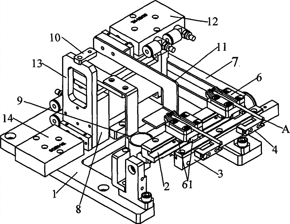
图1是本实用新型自动沾锡装置实施例结构示意图;Fig. 1 is the structural representation of the embodiment of automatic tin dipping device of the present utility model;
图2是本实用新型连接线固定机构输送机构实施例结构示意图;Fig. 2 is a structural schematic diagram of an embodiment of the delivery mechanism of the connecting wire fixing mechanism of the present invention;
图3是本实用新型推料装置实施例结构分解示意图;Fig. 3 is a schematic diagram of an exploded structure of an embodiment of the pushing device of the present invention;
图4是本实用新型自动沾锡装置实施例沾锡状态结构示意图;Fig. 4 is a schematic structural diagram of the tin-staining state of an embodiment of the automatic tin-staining device of the present invention;
图5是本实用新型后导轨实施例结构示意图;Fig. 5 is a structural schematic diagram of an embodiment of the rear guide rail of the utility model;
图6是本实用新型连接线固定机构的固定结构实施例结构示意图;Fig. 6 is a structural schematic diagram of an embodiment of the fixing structure of the connecting wire fixing mechanism of the present invention;
具体实施方式 Detailed ways
为了使要实用新型的目的、技术方案和优点更加清楚,下面将结合本实用新型实施例中的附图,对本实用新型实施例中的技术方案进行清楚、完整地描述,显然,所描述的实施例是实用新型一部分实施例,而不是全部的实施例。基于本实用新型中的实施例,本领域普通技术人员在没有做出创造性劳动的前提下所获得的所有其他实施例,都属于本实用新型保护的范围。In order to make the purpose, technical solutions and advantages of the utility model clearer, the technical solutions in the embodiments of the utility model will be clearly and completely described below in conjunction with the drawings in the embodiments of the utility model. Obviously, the described implementation Examples are some embodiments of the utility model, not all embodiments. Based on the embodiments of the present utility model, all other embodiments obtained by persons of ordinary skill in the art without making creative efforts belong to the scope of protection of the present utility model.
如图1、图2和图3所示,本实用新型提供一种自动沾锡装置实施例。As shown in Figure 1, Figure 2 and Figure 3, the utility model provides an embodiment of an automatic tin dipping device.
该自动沾锡装置包括:输送机构和锡炉(附图未标示)以及协调气动或/和电动器件工作的控制器(附图未标示),该输送机构设有连接线驱动机构、与连接线固定机构6配合的固定导轨机构(附图未标示)和与固定导轨机构平滑连接的活动导轨机构,该活动导轨机构分别与机架活动连接和翻转机构传动连接,所述锡炉位于活动导轨机构一侧机架上。The automatic tin dipping device includes: a conveying mechanism and a tin furnace (not shown in the drawings) and a controller (not shown in the drawings) that coordinates the work of pneumatic or/and electric devices. The fixed guide rail mechanism (not shown in the accompanying drawings) coordinated by the fixed mechanism 6 and the movable guide rail mechanism smoothly connected with the fixed guide rail mechanism. on one side of the rack.
具体地说,所述固定导轨机构包括:采用包括两平行的固定导轨,所述活动导轨机构包括前活动导轨3和后活动导轨2,其中前活动导轨3和后活动导轨2分别与固定导轨机构上的两固定导轨平滑连接;所述锡炉位于后活动导轨2一侧。Specifically, the fixed guide rail mechanism includes: adopting two parallel fixed guide rails, the movable guide rail mechanism includes a front
所述输送机构5包括与连接线固定机构6配合的推料装置53和驱动该推料装置移动的推料气缸50,该推料气缸输50出端通过连杆52与推料装置53配合,其中所述推料装置53包括与该导向部件51配合的推料底座530,该推料底座530上设有活动的推料块532,在该推料块532与推料底座530之间设有弹簧531,该推料块532呈三角形,在该推料块532三角形值斜面的一侧设有与推料底座530配合的限位凸起,由于方该推料块532呈三角形方便在移动完一个连接线固定机构6后向回移动时更容易,设有限位凸起可以避免在弹簧531作用使推料块532出现翻转。所述连接线固定机构6设有与两活动导轨和两固定导轨配合的限位结构61。工作时,当固定有连线A的连接线固定机构6在输送机构5驱动下移动至两活动导轨位置时,由控制器控制推料气缸50停止工作,同时控制翻转驱动机构7驱动前活动导轨3和后活动导轨2同步向锡炉方向作90度翻转,如图4所示。通过适当配置使连接线A的沾锡端与锡炉的焊锡接触,再由翻转驱动机构7使前活动导轨3和后活动导轨2复位后,在控制器的协调下连接线固定机构6在推料气缸50推动下,将沾完焊锡的连接线向前移动,继续对后一连接线固定机构6上的连接线进行沾锡动作。该自动沾锡装置结构简单,通过适当控制焊锡液面可以精确控制沾锡的长度,同时采用自动控制沾锡可以提高沾锡效率,避免人工沾锡效率低,容易引起烫伤现象。The conveying mechanism 5 includes a
在本实施例中,所述自动沾锡装置还包括锡筒9,该锡筒9通过沾锡连杆与固定在锡筒支架上的锡筒升降汽缸8连接。在控制器协调下,使锡筒9和锡筒升降汽缸8与翻转后的沾锡连接线位置相当,当所述锡筒9盛满焊锡时,其焊锡液面始终保持相同高度,通过适当控制锡筒9的高度,可以使锡筒9内的焊锡液面始终保一致,可以实现对沾锡长度精确控制。In this embodiment, the automatic tin dipping device further includes a tin cylinder 9, and the tin cylinder 9 is connected to the tin
在所述锡筒支架上设有沾锡连杆限位部10,可以对锡筒9升起高度进行调节,适合不同沾锡长度要求。The tin canister support is provided with a dipping tin connecting
根据需要可以在所机架上还设有刮锡汽缸12,该刮锡汽缸12输出端与刮板11连接,该刮板11的端部与锡筒9的高度相当,工作时由所述刮锡汽缸12推动刮板11将锡筒9表面锡渣除掉,方更连接线沾锡。According to needs, a
由于连接线固定机构6与前活动导轨3和后活动导轨2配合时有一定间隙,在翻转前活动导轨3和后活动导轨2时其上的连接线固定机构6会发生向一侧移动,造成沾锡精度难以控制,因此在两活动导轨上设有对连接线固定机构6进行固定的固定结构4,如图5和图6所示。Because there is a certain gap when the connecting wire fixing mechanism 6 cooperates with the front
该固定结构4包括与前活动导轨3固定的挡块41,在该挡块41与前活动导轨3之间顺序设有弹性部件43和定位舌42;挡块41与后活动导轨3与固定,在挡块41与后活动导轨2之间顺序设有弹性部件43和定位舌42。所述弹性部件43包括伸缩弹簧或弹片,该弹性部件43使所述定位舌42保持与连接线固定机构6保护一定的压力。所述定位舌42与连接线固定机构6配合端呈梯形425,与弹性部件43接触端设有限位部421,其中定位舌42与连接线固定机构6配合端呈梯形425可以方便连接线固定机构6更好移动到定位舌42的位置,同时可以保护与连接线固定机构6有更大的接触面积,固定连接线固定机构6更牢固,提高连接线粘锡精度;所述限位部421可以避免定位舌42伸出太长影响对连接线固定机构6固定。This fixed structure 4 comprises the
所述机架1还设有锡筒平移汽缸14,该锡筒平移汽缸14输出端与锡筒支架13连接,通过该锡筒平移汽缸14可以调节锡筒的位置。Described
在上述实施例的基础上还提出另一实施例,所述活动导轨机构为一个活动导轨,在该活动导轨固定连接线固定机构6位置对应的固定导轨上设有开口31,该开口31与连接线固定机构6上的限位结构61配合,其他结构不变,其结构更简单。Another embodiment is also proposed on the basis of the above-described embodiment, the movable guide rail mechanism is a movable guide rail, and an
当固定有连线A的连接线固定机构6在输送机构5驱动下沿两固定导轨移动至活动导轨位置时,由控制器控制推料气缸50停止工作,同时控制翻转驱动机构7驱动活动导轨向锡炉方向作90度翻转,由于固定导轨与连接线固定机构6对应位置设有开口31,在活动导轨翻转时,与其中一固定导轨配合的限位结构61通过开口31离开固定导轨。其他动作过程与上述相同。该自动沾锡装置结构简单,通过适当控制焊锡液面可以精确控制沾锡的长度,同时采用自动控制沾锡可以提高沾锡效率,避免人工沾锡效率低,容易引起烫伤现象。When the connecting line fixing mechanism 6 fixed with the connecting line A is driven by the conveying mechanism 5 and moves to the position of the movable guide rail along the two fixed guide rails, the controller controls the pushing
由于连接线固定机构6在翻转时,只有一边与活动导轨配合,在翻转时,连接线固定机构6容易掉落,因此可以在活动导轨上设有上述固定结构4,通过固定结构4可以将连接线固定机构6夹紧,避免翻转时连接线固定机构6脱落。Since the connecting wire fixing mechanism 6 only has one side to cooperate with the movable guide rail when overturning, the connecting wire fixing mechanism 6 is easy to fall off, so the above-mentioned fixing structure 4 can be provided on the movable guiding rail, and the connecting wire can be connected by the fixing structure 4. The wire fixing mechanism 6 is clamped to prevent the connection wire fixing mechanism 6 from falling off when turning over.
在上述实施例中,所述活动导轨机构采用两个相互平行两固定导轨与两活动导轨配合,通过翻转至少一活动导轨实现沾锡。所述活动导轨机构也可以采用一个活动导轨,对应的固定导轨机构也为一个固定导轨,所述活动导轨与固定导轨平滑连接,该活动导轨和固定导轨的截面可以采用工字型,所述连接线固定机构6与活动导轨和固定导轨配合。其他结构和原理都不变,在翻转时连接线固定机构6不会脱离活动导轨,也可以实现对连接线进行自动沾锡形式,其结构更简单。In the above embodiment, the movable guide rail mechanism adopts two parallel fixed guide rails to cooperate with the two movable guide rails, and tin dipping is realized by turning over at least one movable guide rail. The movable guide rail mechanism can also adopt a movable guide rail, and the corresponding fixed guide rail mechanism is also a fixed guide rail. The movable guide rail is smoothly connected with the fixed guide rail. Line fixing mechanism 6 cooperates with movable guide rail and fixed guide rail. Other structures and principles remain the same, the connecting wire fixing mechanism 6 will not break away from the movable guide rail when turned over, and the automatic dipping of the connecting wire can also be realized, and its structure is simpler.
以上实施例仅用以说明本实用新型的技术方案,而非对其限制;尽管参照前述实施例对本实用新型进行了详细的说明,本领域的普通技术人员应当理解:其依然可以对前述各实施例所记载的技术方案进行修改,或者对其中部分技术特征进行等同替换,而这些修改或替换,并不使相应技术方案的本质脱离本实用新型各实施例技术方案的精神和范围。The above embodiments are only used to illustrate the technical solutions of the present utility model, and are not intended to limit it; although the utility model has been described in detail with reference to the foregoing embodiments, those of ordinary skill in the art should understand that: it can still be applied to the foregoing embodiments The technical solutions described in the examples are modified, or some of the technical features are equivalently replaced, and these modifications or replacements do not make the essence of the corresponding technical solutions deviate from the spirit and scope of the technical solutions of the various embodiments of the present invention.
Claims (10)
Priority Applications (1)
| Application Number | Priority Date | Filing Date | Title |
|---|---|---|---|
| CN2012201260905U CN202491001U (en) | 2012-03-21 | 2012-03-21 | Automatic tinning device |
Applications Claiming Priority (1)
| Application Number | Priority Date | Filing Date | Title |
|---|---|---|---|
| CN2012201260905U CN202491001U (en) | 2012-03-21 | 2012-03-21 | Automatic tinning device |
Publications (1)
| Publication Number | Publication Date |
|---|---|
| CN202491001U true CN202491001U (en) | 2012-10-17 |
Family
ID=46997244
Family Applications (1)
| Application Number | Title | Priority Date | Filing Date |
|---|---|---|---|
| CN2012201260905U Expired - Lifetime CN202491001U (en) | 2012-03-21 | 2012-03-21 | Automatic tinning device |
Country Status (1)
| Country | Link |
|---|---|
| CN (1) | CN202491001U (en) |
Cited By (2)
| Publication number | Priority date | Publication date | Assignee | Title |
|---|---|---|---|---|
| CN102601482A (en) * | 2012-03-21 | 2012-07-25 | 刘光辉 | Automatic tin staining device |
| CN104772543A (en) * | 2014-12-27 | 2015-07-15 | 东莞市三才电子设备科技有限公司 | Full-automatic soldering equipment |
-
2012
- 2012-03-21 CN CN2012201260905U patent/CN202491001U/en not_active Expired - Lifetime
Cited By (3)
| Publication number | Priority date | Publication date | Assignee | Title |
|---|---|---|---|---|
| CN102601482A (en) * | 2012-03-21 | 2012-07-25 | 刘光辉 | Automatic tin staining device |
| CN102601482B (en) * | 2012-03-21 | 2015-06-17 | 刘光辉 | Automatic tin staining device |
| CN104772543A (en) * | 2014-12-27 | 2015-07-15 | 东莞市三才电子设备科技有限公司 | Full-automatic soldering equipment |
Similar Documents
| Publication | Publication Date | Title |
|---|---|---|
| CN102601482B (en) | Automatic tin staining device | |
| CN103480936B (en) | Full-automatic soldering machine | |
| CN203664882U (en) | Automatic dip soldering machine | |
| CN202491001U (en) | Automatic tinning device | |
| CN103223546B (en) | A welding rod automatic flat welding device | |
| CN112025023A (en) | Convenient circuit board intelligence welding set of material loading | |
| JP2015153715A (en) | Method of manufacturing electrical wire with terminal | |
| CN206370389U (en) | The parallel-moving type silver point of contact of breaker component assembly equipment and static contact docking facilities | |
| US11000912B2 (en) | Automatic solder paste feeding system | |
| CN113751817B (en) | Dip soldering device and corresponding full-automatic dip soldering machine | |
| CN204122873U (en) | Dip-soldering machine | |
| CN207493929U (en) | For the device of PCB tin creams spraying | |
| CN203936539U (en) | Automatic welding machine | |
| CN103223545B (en) | Control method for automatic flat welding device for welding rods | |
| CN118951534B (en) | Field effect tube welding device and method thereof | |
| CN203956320U (en) | Stitch welding machine | |
| CN109089384B (en) | A kind of method for repairing and mending of liquid metal printer and liquid metal printing product | |
| CN203667510U (en) | Feeding mechanism of toggle switch wiring machine | |
| CN101306484A (en) | Automatic welding device for flow line | |
| CN208584077U (en) | Automatic tin soldering device | |
| CN205551720U (en) | Phone jack connector welding set | |
| CN205056356U (en) | A automatic fat liquoring device that is used for protein crystallization board sealed | |
| CN113732430B (en) | Full-automatic dip soldering machine | |
| CN215238399U (en) | Dragging and welding equipment acting on copper foil of SATA cable port | |
| CN209078695U (en) | A kind of "-" type 6PIN pin remover moves back nail locating and clamping apparatus |
Legal Events
| Date | Code | Title | Description |
|---|---|---|---|
| C14 | Grant of patent or utility model | ||
| GR01 | Patent grant | ||
| EE01 | Entry into force of recordation of patent licensing contract |
Assignee: Shenzhen Zhonghai robot Co., Ltd. Assignor: Liu Guanghui Contract record no.: 2013440020307 Denomination of utility model: Automatic tin staining device Granted publication date: 20121017 License type: Exclusive License Record date: 20131106 |
|
| LICC | Enforcement, change and cancellation of record of contracts on the licence for exploitation of a patent or utility model | ||
| CX01 | Expiry of patent term |
Granted publication date: 20121017 |
|
| CX01 | Expiry of patent term |