CN202490856U - Bus-bar bending machine - Google Patents
Bus-bar bending machine Download PDFInfo
- Publication number
- CN202490856U CN202490856U CN2012200658563U CN201220065856U CN202490856U CN 202490856 U CN202490856 U CN 202490856U CN 2012200658563 U CN2012200658563 U CN 2012200658563U CN 201220065856 U CN201220065856 U CN 201220065856U CN 202490856 U CN202490856 U CN 202490856U
- Authority
- CN
- China
- Prior art keywords
- splint
- fan
- clamping plate
- shaped
- rectangular
- Prior art date
- Legal status (The legal status is an assumption and is not a legal conclusion. Google has not performed a legal analysis and makes no representation as to the accuracy of the status listed.)
- Expired - Fee Related
Links
Images


Landscapes
- Bending Of Plates, Rods, And Pipes (AREA)
Abstract
一种能够方便在母线排上折与横向折弯距离小的竖向弯的母线排折弯机,包括机架和液压缸,机架上铰接有固定支座,固定支座的下端连接有扇形夹板,固定支座的上端铰接有活动板,活动板上固定连接有长方形夹板,长方形夹板与扇形夹板相对应,长方形夹板与扇形夹板开有套孔,长方形夹板与扇形夹板之间夹有半圆柱形铁杆,半圆柱形铁杆的端部位于套孔内,长方形夹板与扇形夹板之间设计有顶子,顶子的后端与液压缸固定连接。
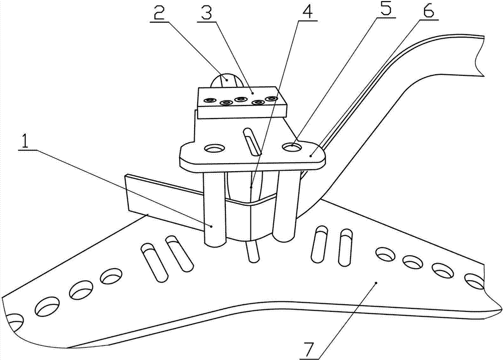
A bus bar bending machine capable of conveniently bending the bus bar up and bending vertically with a small distance between horizontal bending, including a frame and a hydraulic cylinder, the frame is hinged with a fixed support, and the lower end of the fixed support is connected with a fan-shaped The splint, the upper end of the fixed support is hinged with a movable plate, and the movable plate is fixedly connected with a rectangular splint. The rectangular splint corresponds to the fan-shaped splint. Shaped iron rod, the end of the semi-cylindrical iron rod is located in the sleeve hole, a top is designed between the rectangular splint and the fan-shaped splint, and the rear end of the top is fixedly connected with the hydraulic cylinder.
Description
Claims (1)
Priority Applications (1)
| Application Number | Priority Date | Filing Date | Title |
|---|---|---|---|
| CN2012200658563U CN202490856U (en) | 2012-02-27 | 2012-02-27 | Bus-bar bending machine |
Applications Claiming Priority (1)
| Application Number | Priority Date | Filing Date | Title |
|---|---|---|---|
| CN2012200658563U CN202490856U (en) | 2012-02-27 | 2012-02-27 | Bus-bar bending machine |
Publications (1)
| Publication Number | Publication Date |
|---|---|
| CN202490856U true CN202490856U (en) | 2012-10-17 |
Family
ID=46997100
Family Applications (1)
| Application Number | Title | Priority Date | Filing Date |
|---|---|---|---|
| CN2012200658563U Expired - Fee Related CN202490856U (en) | 2012-02-27 | 2012-02-27 | Bus-bar bending machine |
Country Status (1)
| Country | Link |
|---|---|
| CN (1) | CN202490856U (en) |
Cited By (2)
| Publication number | Priority date | Publication date | Assignee | Title |
|---|---|---|---|---|
| CN103464539A (en) * | 2013-08-27 | 2013-12-25 | 国家电网公司 | Bending device special for corner grounding flat bars |
| CN106180292A (en) * | 2016-08-29 | 2016-12-07 | 安徽中电兴发与鑫龙科技股份有限公司 | A kind of copper bar bending tool and using method thereof |
-
2012
- 2012-02-27 CN CN2012200658563U patent/CN202490856U/en not_active Expired - Fee Related
Cited By (3)
| Publication number | Priority date | Publication date | Assignee | Title |
|---|---|---|---|---|
| CN103464539A (en) * | 2013-08-27 | 2013-12-25 | 国家电网公司 | Bending device special for corner grounding flat bars |
| CN103464539B (en) * | 2013-08-27 | 2015-12-09 | 国家电网公司 | The special apparatus for bending of corner ground connection band iron |
| CN106180292A (en) * | 2016-08-29 | 2016-12-07 | 安徽中电兴发与鑫龙科技股份有限公司 | A kind of copper bar bending tool and using method thereof |
Similar Documents
| Publication | Publication Date | Title |
|---|---|---|
| CN205074374U (en) | Steel sheet bending device | |
| CN204866955U (en) | Tube -bending machine | |
| CN201776317U (en) | Adjusting device for upwarp deformation of large component of stainless steel car roof | |
| CN213409922U (en) | A sheet metal bending machine for watch box production | |
| CN202411163U (en) | Copper bar bending device | |
| CN104043704A (en) | Hydraulic metal pipe U shape arc-bending machine | |
| CN203508697U (en) | Multi-model Z-shape bending machine capable of being debugged | |
| CN211758072U (en) | Support riveting connects tight frock that expands | |
| CN104511710A (en) | Front-and-back compressing and positioning device used for welding automobile steering support reinforcing stand assembly | |
| CN202129352U (en) | Bending mould of metal plate bending machine tool | |
| CN203873377U (en) | Bed sheet tidying device | |
| CN205165455U (en) | Roll curved device | |
| CN203343230U (en) | Hydraulic plate bender | |
| CN204953609U (en) | Bend and use press | |
| CN202921706U (en) | Simple busbar bender | |
| CN203417961U (en) | Straightening mechanism | |
| CN203737909U (en) | Forged workpiece fixing device | |
| CN203140521U (en) | Oil hydraulic tool | |
| CN202411158U (en) | straightener for short steel tubes of scaffold | |
| CN103521573A (en) | Adjustable multiple-type Z shape bending machine | |
| CN200995238Y (en) | Vertical bending machine | |
| CN202072290U (en) | Glass turning floating structure device | |
| CN202556286U (en) | Reinforcing steel bar clamping structure for reinforcing steel bar clamping device | |
| CN203695685U (en) | Portable busbar bending device | |
| CN204504056U (en) | Portable reinforcing steel bar prebending machine |
Legal Events
| Date | Code | Title | Description |
|---|---|---|---|
| C14 | Grant of patent or utility model | ||
| GR01 | Patent grant | ||
| ASS | Succession or assignment of patent right |
Owner name: STATE ELECTRIC NET CROP. Effective date: 20130724 |
|
| C41 | Transfer of patent application or patent right or utility model | ||
| COR | Change of bibliographic data |
Free format text: CORRECT: ADDRESS; FROM: 277100 ZAOZHUANG, SHANDONG PROVINCE TO: 277000 ZAOZHUANG, SHANDONG PROVINCE |
|
| TR01 | Transfer of patent right |
Effective date of registration: 20130724 Address after: 277000 the Yellow River Road, Xuecheng District, Shandong, No. 999, No. Patentee after: Tai'an Power Supply Co., Ltd. of Shandong Electric Power Corporation Patentee after: State Grid Corporation of China Address before: 277100 Zaozhuang power supply company, No. 60 Guangming Middle Road, Shizhong District, Zaozhuang, Shandong Patentee before: Tai'an Power Supply Co., Ltd. of Shandong Electric Power Corporation |
|
| C17 | Cessation of patent right | ||
| CF01 | Termination of patent right due to non-payment of annual fee |
Granted publication date: 20121017 Termination date: 20140227 |