CN202490462U - High-efficient extraction tank - Google Patents
High-efficient extraction tank Download PDFInfo
- Publication number
- CN202490462U CN202490462U CN2012200851024U CN201220085102U CN202490462U CN 202490462 U CN202490462 U CN 202490462U CN 2012200851024 U CN2012200851024 U CN 2012200851024U CN 201220085102 U CN201220085102 U CN 201220085102U CN 202490462 U CN202490462 U CN 202490462U
- Authority
- CN
- China
- Prior art keywords
- chamber
- clarification chamber
- extraction tank
- extraction
- clarification
- Prior art date
- Legal status (The legal status is an assumption and is not a legal conclusion. Google has not performed a legal analysis and makes no representation as to the accuracy of the status listed.)
- Expired - Fee Related
Links
Images


Classifications
-
- Y—GENERAL TAGGING OF NEW TECHNOLOGICAL DEVELOPMENTS; GENERAL TAGGING OF CROSS-SECTIONAL TECHNOLOGIES SPANNING OVER SEVERAL SECTIONS OF THE IPC; TECHNICAL SUBJECTS COVERED BY FORMER USPC CROSS-REFERENCE ART COLLECTIONS [XRACs] AND DIGESTS
- Y02—TECHNOLOGIES OR APPLICATIONS FOR MITIGATION OR ADAPTATION AGAINST CLIMATE CHANGE
- Y02P—CLIMATE CHANGE MITIGATION TECHNOLOGIES IN THE PRODUCTION OR PROCESSING OF GOODS
- Y02P10/00—Technologies related to metal processing
- Y02P10/20—Recycling
Landscapes
- Sampling And Sample Adjustment (AREA)
Abstract
本实用新型公开了一种高效萃取槽,包括混合室(5)、澄清室(6)、槽盖、挡板(3),所述混合室(5)连接澄清室(6),在混合室(5)侧壁开有进料口(1),其特征在于:还包括调节管(4),所述调节管(4)安装在澄清室(6)中,所述挡板(3)安装在澄清室(6)中调节管(4)对面。本实用新型能快速调节澄清室的液位,从而很好的控制水相和萃取相的比例,萃取效率高,且能有效的消除乳化现象,有力保证产品品质。
The utility model discloses a high-efficiency extraction tank, which comprises a mixing chamber (5), a clarification chamber (6), a tank cover, and a baffle (3). The mixing chamber (5) is connected to the clarification chamber (6). (5) There is a feed inlet (1) on the side wall, which is characterized in that it also includes a regulating pipe (4), the regulating pipe (4) is installed in the clarification chamber (6), and the baffle (3) is installed Opposite the regulating pipe (4) in the clarification chamber (6). The utility model can quickly adjust the liquid level of the clarification chamber, so that the ratio of the water phase and the extraction phase can be well controlled, the extraction efficiency is high, the emulsification phenomenon can be effectively eliminated, and the product quality can be strongly guaranteed.
Description
技术领域 technical field
本实用新型涉及一种萃取槽,尤其涉及一种高效萃取槽。The utility model relates to an extraction tank, in particular to an efficient extraction tank.
背景技术 Background technique
目前,市场上常见的萃取槽存在因无法调整液位而导致容易出现乳化的现象,这给整个生产过程带来很大影响,同时它也不能很好的控制水相和萃取相的比例,萃取效率低,影响产品品质。At present, the common extraction tanks on the market are prone to emulsification due to the inability to adjust the liquid level, which has a great impact on the entire production process. At the same time, it cannot well control the ratio of the water phase to the extraction phase. Low efficiency affects product quality.
发明内容 Contents of the invention
本实用新型的目的在于克服现有技术的不足,提供一种高效萃取槽。The purpose of the utility model is to overcome the deficiencies of the prior art and provide a high-efficiency extraction tank.
为达到上述目的,本实用新型所采用的技术手段是,一种高效萃取槽,包括混合室、澄清室、槽盖、挡板、调节管,所述混合室连接澄清室,在混合室侧壁开有进料口,所述调节管安装在澄清室中,所述挡板安装在澄清室中调节管对面。In order to achieve the above purpose, the technical means adopted by the utility model is, a high-efficiency extraction tank, including a mixing chamber, a clarification chamber, a tank cover, a baffle, and a regulating tube, the mixing chamber is connected to the clarification chamber, and There is a feeding port, the regulating pipe is installed in the clarification chamber, and the baffle is installed opposite to the regulating pipe in the clarification chamber.
进一步的,所述澄清室侧壁设置有视镜。Further, the side wall of the clarification chamber is provided with a sight glass.
进一步的,所述槽盖上开有用于取样的取样口和搅拌口。Further, the tank cover is provided with a sampling port and a stirring port for sampling.
本实用新型的有益效果是:通过在澄清室内设置调节管,能够方便快速地调节澄清室的液位,从而很好的控制水相和萃取相的比例,萃取效率高,且能有效的消除乳化现象,有力保证产品品质。The beneficial effects of the utility model are: by setting the regulating tube in the clarification chamber, the liquid level of the clarification chamber can be adjusted conveniently and quickly, so that the ratio of the water phase and the extraction phase can be well controlled, the extraction efficiency is high, and the emulsification can be effectively eliminated. Phenomenon, effectively guarantee product quality.
附图说明 Description of drawings
下面结合附图和实施例对本实用新型进一步说明。Below in conjunction with accompanying drawing and embodiment the utility model is further described.
图1为本实用新型的主视图;Fig. 1 is the front view of the utility model;
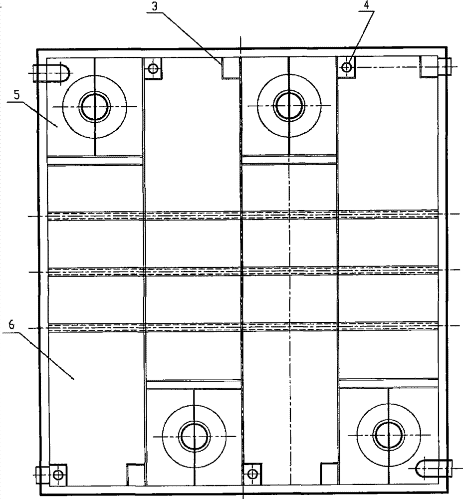
图2为本实用新型的俯视图;Fig. 2 is the top view of the utility model;
图3为本实用新型槽盖示意图。Fig. 3 is a schematic diagram of the tank cover of the present invention.
图中标记为:1、进料口,2、视镜,3、挡板,4、调节管,5、混合室,6、澄清室,7、取样口,8、搅拌口。The marks in the figure are: 1. Feed inlet, 2. Sight glass, 3. Baffle, 4. Regulating tube, 5. Mixing chamber, 6. Clarifying chamber, 7. Sampling port, 8. Stirring port.
具体实施方式 Detailed ways
如图1、图2、图3所示,一种高效萃取槽,包括混合室5、澄清室6、槽盖、挡板3、调节管4,所述混合室5连接澄清室6,在混合室5侧壁开有进料口1,所述调节管4安装在澄清室6中,所述挡板3安装在澄清室6中调节管4对面。As shown in Figures 1, 2 and 3, a high-efficiency extraction tank includes a mixing chamber 5, a clarification chamber 6, a tank cover, a baffle plate 3, and a regulating pipe 4, and the mixing chamber 5 is connected to the clarification chamber 6. The side wall of the chamber 5 is provided with a feed inlet 1 , the regulating pipe 4 is installed in the clarification chamber 6 , and the baffle plate 3 is installed in the clarification chamber 6 opposite to the regulating pipe 4 .
进一步的,所述澄清室6侧壁设置有视镜2。Further, a sight glass 2 is provided on the side wall of the clarification chamber 6 .
进一步的,所述槽盖上开有用于取样的取样口7和搅拌口8。Further, a
物料由进料口1进入混合室5,混合后进入澄清室6,通过视镜2可以观察澄清室内混合相分层情况,通过调节管4可以调节澄清室的液位,槽盖上开有用于取样的取样口7和搅拌口8,萃取槽中水相和有机相采用逆流方式进行萃取,采用逆流方式进行萃取,萃取效率高。The material enters the mixing chamber 5 from the feed port 1, and enters the clarification chamber 6 after mixing. The stratification of the mixed phase in the clarification chamber can be observed through the sight glass 2, and the liquid level of the clarification chamber can be adjusted through the regulating tube 4. There is a hole on the tank cover for The
Claims (3)
Priority Applications (1)
| Application Number | Priority Date | Filing Date | Title |
|---|---|---|---|
| CN2012200851024U CN202490462U (en) | 2012-03-09 | 2012-03-09 | High-efficient extraction tank |
Applications Claiming Priority (1)
| Application Number | Priority Date | Filing Date | Title |
|---|---|---|---|
| CN2012200851024U CN202490462U (en) | 2012-03-09 | 2012-03-09 | High-efficient extraction tank |
Publications (1)
| Publication Number | Publication Date |
|---|---|
| CN202490462U true CN202490462U (en) | 2012-10-17 |
Family
ID=46996707
Family Applications (1)
| Application Number | Title | Priority Date | Filing Date |
|---|---|---|---|
| CN2012200851024U Expired - Fee Related CN202490462U (en) | 2012-03-09 | 2012-03-09 | High-efficient extraction tank |
Country Status (1)
| Country | Link |
|---|---|
| CN (1) | CN202490462U (en) |
Cited By (2)
| Publication number | Priority date | Publication date | Assignee | Title |
|---|---|---|---|---|
| CN110714118A (en) * | 2018-12-28 | 2020-01-21 | 中核沽源铀业有限责任公司 | EC-D type extraction tank for uranium hydrometallurgy |
| CN117089701A (en) * | 2022-05-12 | 2023-11-21 | 核工业北京化工冶金研究院 | Uranium purification extraction tank and uranium purification extraction tank emulsion reduction and transfer method |
-
2012
- 2012-03-09 CN CN2012200851024U patent/CN202490462U/en not_active Expired - Fee Related
Cited By (2)
| Publication number | Priority date | Publication date | Assignee | Title |
|---|---|---|---|---|
| CN110714118A (en) * | 2018-12-28 | 2020-01-21 | 中核沽源铀业有限责任公司 | EC-D type extraction tank for uranium hydrometallurgy |
| CN117089701A (en) * | 2022-05-12 | 2023-11-21 | 核工业北京化工冶金研究院 | Uranium purification extraction tank and uranium purification extraction tank emulsion reduction and transfer method |
Similar Documents
| Publication | Publication Date | Title |
|---|---|---|
| CN203333653U (en) | Novel anaerobic fermentation device | |
| CN202237294U (en) | Single-effect concentrator discharge port material taking detection device | |
| CN205188256U (en) | Fruit wine control by temperature change fermentation cylinder | |
| CN204385261U (en) | A kind of ion type rareearth ore reverse feed liquor leaching ore deposit device | |
| CN203534858U (en) | Portable sampler with filter screen | |
| CN201245644Y (en) | Marsh gas fermentation tank with gas-collecting hood for realizing unpowered automatic stirring | |
| CN203291563U (en) | Liquid water glass discharge buffer tank | |
| CN202988695U (en) | Controllable constant-pressure dropping funnel | |
| CN203820783U (en) | Double-tube type overflowing system of biogas fermentation tank | |
| CN202125934U (en) | Hydrocone type simple steaming device | |
| CN202752265U (en) | Electrolytic manganese substandard manganese cleaning machine | |
| CN103923820B (en) | A kind of marsh-gas fermentation tank double hose overflow system | |
| CN207877293U (en) | Resin waste liquid recovery apparatus | |
| CN201553601U (en) | Sterile liquid balancing tank | |
| CN206808390U (en) | A kind of black goat cultivates water saving tank | |
| CN203938665U (en) | A kind of Solid/liquid two purpose Brewing equipment | |
| CN204165788U (en) | A kind of precipitable simple water-fetching device | |
| CN202128950U (en) | Defoaming device for crystallizing tank | |
| CN202683115U (en) | Automatic stirring device | |
| CN205774721U (en) | A kind of energy-conservation rare earth extraction slot device | |
| CN202315395U (en) | Chinese medicine extraction tank with external extractor | |
| CN204918833U (en) | Vapor diffusion crystal bring -up glassware | |
| CN203346397U (en) | Fermentation tank with gas flowmeter | |
| CN203957688U (en) | A kind of Multifunction palette | |
| CN202962649U (en) | Magnetic field system for removing iron impurities in aluminum liquid |
Legal Events
| Date | Code | Title | Description |
|---|---|---|---|
| C14 | Grant of patent or utility model | ||
| GR01 | Patent grant | ||
| CF01 | Termination of patent right due to non-payment of annual fee |
Granted publication date: 20121017 Termination date: 20160309 |
|
| CF01 | Termination of patent right due to non-payment of annual fee |