The hospital air disinfector
Technical field
This utility model relates to air sterillization sterilization technology field, particularly can be widely used in a kind of hospital air disinfector in special places such as hospital or pharmaceutical production workshop.
Background technology
As everyone knows, the room air in special places such as hospital, pharmaceutical production workshop is required than higher, particularly higher to the ward air conditional request of being in hospital of hospital; Yet present circumstances is that the condition of being in hospital of hospital is poor; Need at least two perhaps more patients to stay in ward, especially a patients with infectious diseases and family members thereof, accompany and attend to, and some epidemic virus or pathogenic bacteria; How to prevent cross infection, and the prevention disinfection just seems particularly important.At present, air cleaning adopts air filter to filter mostly, and what effect antibacterial, virus etc. is not almost had.To the sterilization of air, air Sterilization and Disinfection Equipment or device are generally arranged, but complex structure, energy consumption is big, and maintenance cost is high, is unfavorable for applying.Therefore, present stage presses for simple in structure, and is easy to use, and disinfecting time is short, and sterilization is thorough, but the sterilisation temp free adjustment is fit to places such as hospital, pharmaceutical production workshop, also is fit to a kind of hospital air disinfector that general family uses simultaneously.
Summary of the invention
The purpose of this utility model is: improve to the ubiquitous problem of prior art, provide rational in infrastructure, easy to use, cost is low, and disinfecting time is short, and sterilization is thorough, and sterilisation temp can freely regulated a kind of hospital air disinfector.
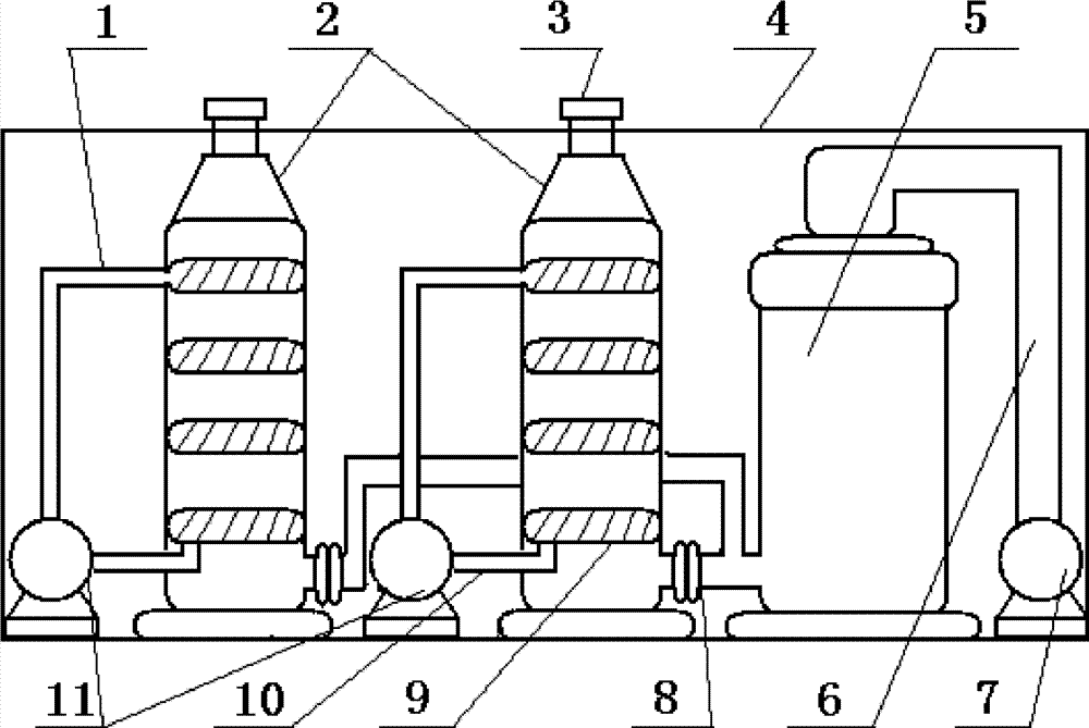
This utility model solves the technical scheme that its technical problem adopted: a kind of hospital air disinfector; The air disinfector 5, chiller 2, circulating pump 7 and the circulating pump 11 that comprise housing 4 and interior setting thereof; It is characterized in that: air disinfector 5 is designed to adopt housing jacket layer 19, middle jacket layer 18 and interior jacket layer 17 three-deckers of infrared ray high-temperature sterilization; Interior jacket layer 17 and interior infrared ray heating tube 21 thereof and the middle jacket layer 18 of housing jacket layer 19 and 17 settings of interior jacket layer that this air disinfector is installed on housing jacket layer 19 upper end covers by housing jacket layer 19, through studdle 13 and hold-down nut 12 are formed, and be as shown in Figure 2.
Be respectively equipped with air inlet 15 and venthole 20 on the upper end cover of interior jacket layer 17 upper end corresponding shell jacket layer 19 and the bottom end cover of interior jacket layer 17; Air inlet 15 and venthole 20 the position is set just corresponding between the infrared ray heating tube 21 and the interstitial site as air conductive channel 23 of 17 of they and interior jacket layers; And the air inlet 15 at housing jacket layer 19 upper end covers is respectively equipped with the gas outlet 8 of drawing phoenix tube 14 and high temperature air of bringing QI KOU 16 into the bottom, side, and is as shown in Figure 2.
Being equipped with the gap between interior jacket layer 17 bottom end covers and housing jacket layer 19 bottom end covers and between middle jacket layer 18 and housing jacket layer 19 upper end covers flows and air conducting passage 22 as air.As shown in Figure 2.Chiller in the present technique is that the high-temperature sterilization air is carried out evenly entering indoor use after water cooling cooling reaches the temperature that human body can adapt to; And indoor used air is delivered to corresponding heater through circulating pump 7 again, makes their high-temperature sterilizations 3 ~ 10 seconds in heater, enters in the atmosphere then.
The operation principle and the work process of present technique are: at first; Outdoor fresh air is through the air inlet 15 on the 19 layers of upper end cover of air inlet 16, housing overcoat that draw phoenix tube 14; Get in the interior jacket layer 17 of infrared ray high temperature air disinfector 5, through the high-temperature sterilization sterilization of infrared ray heating tube 21, typical temperature is about 500 ℃; Pure air after sterilizing through the high-temperature sterilization of infrared ray heating tube 21; Get into the bottom end cover of interior jacket layer 17 and the high temperature air flow-guiding channel 22 between the middle jacket layer 18 through the venthole on the bottom end cover of interior jacket layer 17 20, flow from bottom to top in the high temperature air flow-guiding channel 22 between middle jacket layer 18 and interior jacket layer 17 then, when flowing to the upper end cover of housing jacket layer 19; From top to bottom flow in the high temperature air flow-guiding channel 22 between housing jacket layer 19 and middle jacket layer 18 again after changing direction (an angle of 90 degrees); Until 8 places, (high temperature) gas outlet of housing jacket layer 19 lower ends then get in the chiller 2, (chiller 2 can be two or more to get into chiller 2; Present technique is two; Be connected with 8 places, gas outlet simultaneously, improve cooling work efficient like this) after, normally handle through the cooling of 4 layers of (perhaps being called 4 sections) structure; Drop in temperature (promptly arriving the temperature that human body can adapt to) after the temperature that is fit to human body, evenly enter indoor use in gas outlet 3 through chiller 2.And indoor used air is delivered to corresponding heater through circulating pump 7 again, makes their high-temperature sterilizations 3 ~ 10 seconds in heater, enters in the atmosphere then.
Present technique is compared with prior art, has simple in structurely, easy to use, and disinfecting time is short, sterilization thoroughly, but the sterilisation temp free adjustment is applicable to characteristics such as place use such as hospital, pharmaceutical production workshop, food processing and various houses dwelling house.
Description of drawings
Fig. 1 is the population structure sketch map of this utility model.
Fig. 2 is the population structure sketch map of the air disinfector 5 of this utility model.
Among the figure: 1 circulating line; 2 chillers; 3 gas outlets (chiller gas outlet); 4 housings; 5 air disinfectors (infrared ray high temperature air disinfector); 6 admission lines; 7 circulating pumps; 8 gas outlets (high temperature gas outlet); The 9 cooling networks of rivers; 10 connect pipeline; 11 circulating pumps; 12 hold-down nuts; 13 studdles; 14 draw phoenix tube (air inlet shell); 15 air inlets; 16 air inlets; Jacket layer in 17; Jacket layer in 18; 19 housing jacket layer; 20 ventholes; 21 infrared ray heating tubes; 22 air conducting passages (high temperature air flow-guiding channel); 23 air conductive channel (high temperature air flow-guiding channel).
The specific embodiment
The most preferred embodiment of this utility model; Shown in Fig. 1-2; A kind of hospital air disinfector; The air disinfector 5, chiller 2, circulating pump 7 and the circulating pump 11 that comprise housing 4 and interior setting thereof; It is characterized in that: air disinfector 5 is designed to adopt housing jacket layer 19, middle jacket layer 18 and interior jacket layer 17 three-deckers of infrared ray high-temperature sterilization, and interior jacket layer 17 and interior infrared ray heating tube 21 thereof and the middle jacket layer 18 of housing jacket layer 19 and 17 settings of interior jacket layer that this air disinfector is installed on housing jacket layer 19 upper end covers by housing jacket layer 19, through studdle 13 and hold-down nut 12 are formed, and be as shown in Figure 2.
Be respectively equipped with air inlet 15 and venthole 20 on the upper end cover of interior jacket layer 17 upper end corresponding shell jacket layer 19 and the bottom end cover of interior jacket layer 17; Air inlet 15 and venthole 20 the position is set just corresponding between the infrared ray heating tube 21 and the interstitial site as air conductive channel 23 of 17 of they and interior jacket layers; And the air inlet 15 at housing jacket layer 19 upper end covers is respectively equipped with the gas outlet 8 of drawing phoenix tube 14 and high temperature air of bringing QI KOU 16 into the bottom, side, and is as shown in Figure 2.
Being equipped with the gap between interior jacket layer 17 bottom end covers and housing jacket layer 19 bottom end covers and between middle jacket layer 18 and housing jacket layer 19 upper end covers flows and air conducting passage 22 as air.As shown in Figure 2.Chiller in the present technique is that the high-temperature sterilization air is carried out evenly entering indoor use after water cooling cooling reaches the temperature that human body can adapt to; And indoor used air is delivered to corresponding heater through circulating pump 7 again, makes their high-temperature sterilizations 3 ~ 10 seconds in heater, enters in the atmosphere then.