CN202489509U - Middle transversal beam structure of file cabinet - Google Patents
Middle transversal beam structure of file cabinet Download PDFInfo
- Publication number
- CN202489509U CN202489509U CN2011204737038U CN201120473703U CN202489509U CN 202489509 U CN202489509 U CN 202489509U CN 2011204737038 U CN2011204737038 U CN 2011204737038U CN 201120473703 U CN201120473703 U CN 201120473703U CN 202489509 U CN202489509 U CN 202489509U
- Authority
- CN
- China
- Prior art keywords
- cabinet
- main body
- mounting structure
- file cabinet
- jut
- Prior art date
- Legal status (The legal status is an assumption and is not a legal conclusion. Google has not performed a legal analysis and makes no representation as to the accuracy of the status listed.)
- Expired - Lifetime
Links
Images


Abstract
The utility model provides a middle transversal beam structure of a file cabinet, comprising a cabinet body and a transversal beam mounted inside the cabinet. The cabinet includes side face plates, and the transversal beam includes a main body. A cabinet door is installed on the transversal beam, and assembly structures are provided between the main body and the cabinet door. Grooves are provided on inner walls of the side face plates. The main body is formed with a bended one-piece structure. Protrusions matching with the grooves are arranged in the middle of the main body. According to the utility model, the middle transversal beam structure has a simple structure, convenient installation, and high bearing strength, and the one-piece structure saves working operations and materials, simplifies the overall structure of the transversal beam, facilitates the installation and provides sufficient strength.
Description
Technical field
The utility model relates to a kind of cabinet body structure, particularly a kind of mounting structure that is used for the file cabinet intermediate transverse girder.
Technical background
At present, file cabinet on the market and file cabinet adopts knockdown structure, and existing steel file cabinet has two kinds of integral solder cabinet and dismantled and assembled cabinets.Though the integral solder cabinet has good steadiness, hard transportation, particularly transportation at a distance, cost is very high.Existing dismantled and assembled file cabinet or complex structure like Chinese patent ZL03242499.X, disclose a kind of dismantled and assembled file cabinet; By sky plate, base plate, left plate, right plate, and be installed in left back board, right back board, left front door, the right front door between day plate and the base plate and be installed in the some movable laminate formation on the left and right side plate, four of plate and base plate jiaos all are vertically installed with square tube in the sky; Be provided with the dead slot that is complementary with square tube on the two vertical sides of left and right side plate; Thereby square tube is inserted in the dead slot top and the bottom that sky plate, base plate is respectively fixed to left side plate respectively, such file cabinet need be provided with one with big framework such as file cabinet, intermediate transverse girder can be installed on the framework; This kind structure; Not only wasted wide variety of materials, structure is more complicated also, and need utilize a large amount of screws perhaps to be bolted between crossbeam and the framework; Be unfavorable for conveniently dismounting, structure is also insecure.
Summary of the invention
In order to solve the deficiency of prior art, it is a kind of simple in structure, easy for installation that the utility model provides, the file cabinet beam structure that bearing strength is bigger.
The utility model solves the technical scheme that its technical problem adopted:
Horizontal mounting structure in a kind of file cabinet comprises cabinet and is installed in the inner crossbeam of cabinet that said cabinet includes side panel; Said crossbeam includes main body; The cabinet door is installed on the said crossbeam, is provided with assembly structure between said main body and the said cabinet door, said side panel inwall is provided with groove; Said main body is the structure that one is bent to form, and said main body middle part has the jut with said groove fit.
Improvement as technique scheme; Has the flanging that cooperates with said file cabinet lower floor cabinet door on the said body front end vertical direction; Has the bending edge of placing said dividing plate on the said body rear horizontal direction; Utilize integrated flanging and bending edge directly to be used for placing dividing plate and cabinet door, the use of having saved screw or bolt.
Further, two ends, said jut bottom are provided with the reinforcement button with said groove fit, and said reinforcement button is fixed on the side panel through screw, strengthens button and can improve cooperation intensity, makes crossbeam and side panel to be fastenedly connected.
Further, said jut bottom is provided with the lining beam that is used to increase bearing strength, is used for the bearing capacity of web beam.
Further, said jut is the staggered structure of horizontal convex-concave, and said assembly structure is that said cabinet door is a sliding door; Said cabinet door bottom is equipped with pulley assembly, and said pulley assembly comprises pulley bracket and be installed in the pulley on the pulley bracket that said pulley is provided with slot rolling; Said jut back has the depressed part of the staggered shape of corresponding convex-concave, and said depressed part middle part has the track that cooperates with said slot rolling, and said crossbeam is by one-body molded completion; Has the protruding part of bending; Can be utilized as mobile mounting structure, reduce the operation of processing, save material.
The beneficial effect of the utility model: the utility model provides a kind of simple in structure, easy for installation, the file cabinet beam structure that bearing strength is bigger; Because it is one-body molded that the utility model adopts; Not only saved operation, and reduced material, whole relatively simple for structure of crossbeam; In that install also can be convenient, intensity is also enough.
Description of drawings
Below in conjunction with accompanying drawing and embodiment the utility model is described further.
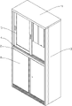
Fig. 1 is the structural representation of the utility model user mode;
Fig. 2 is the structural representation of the utility model;
Fig. 3 is the structural representation of another angle of the utility model;
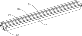
Fig. 4 is the mounting structure sketch map of the utility model;
Fig. 5 is the partial view at the A place of Fig. 4;
Fig. 6 is the utility model mounting structure exploded view;
Fig. 7 is the structural representation of the utility model pulley and track.
The specific embodiment
With reference to Fig. 1 ~ Fig. 7, horizontal mounting structure in a kind of file cabinet, the crossbeam 2 that comprises cabinet 1 and be installed in cabinet 1 inside; Said cabinet 1 includes side panel 3, and said crossbeam 2 includes main body 4, on the said crossbeam 2 cabinet door 5 is installed; Be provided with assembly structure between said main body 4 and the said cabinet door 5; Said side panel 3 inwalls are provided with groove 6, the structure that said main body 4 is shaped for the one bending, and said main body 4 middle parts have the jut 7 that cooperates with said groove 6.
In the present embodiment, because said main body 4 structure that is formed in one, therefore has the flanging 9 that cooperates with said file cabinet lower floor cabinet door 8 on the said main body 4 front end vertical directions; Have the bending edge 11 of placing said dividing plate 10 on the said main body 4 rear end horizontal directions, can not utilize screw or bolt to fix dividing plate 10, and have the flanging 9 that holds lower floor's cabinet door 8; Simplified mounting structure, the force intensity that receives for further web beam 2 is provided with the reinforcement button 12 that cooperates with said groove 6 at two ends, said jut 7 bottom; In an embodiment, said side panel 3 also is to adopt one-body molded processing, therefore; Monologue story-telling with gestures groove 6 is also through being bent to form; Said reinforcement button 12 is fixed on the side panel 3 through screw, has strengthened bonding strength, same reason; Be provided with the lining beam 13 that is used to increase bearing strength in said jut 7 bottoms, can play the effect that increases crossbeam 2 support forces.
In addition, when the main body of crossbeam 24 was one-body molded, the structure of said jut 7 was that horizontal convex-concave is staggered; The cabinet door assembly structure on said cabinet top is that said cabinet door 5 is sliding door, and is attractive in appearance for ease, can adopt the glass type sliding door; Said cabinet door 5 bottoms are equipped with pulley assembly 14, and said pulley assembly 14 comprises pulley bracket 15 and be installed in the pulley 16 on the pulley bracket 15 that said pulley 16 is provided with slot rolling 17; Said jut 7 backs have the depressed part 18 of the staggered shape of corresponding convex-concave, and said depressed part 18 middle parts have the track 19 that cooperates with said slot rolling 17, when production and processing; Also can on the utility model, install a stiffener, can utilize stiffener structure, through cabinet door and the hinged mode of panel; Also can install and cover box-like cabinet door; Two kinds of cabinet door structures can be processed through one very easily and realize that mounting structure is also fairly simple, and intensity is also relatively enough.
The above be the utility model preferred embodiment, it does not constitute the restriction to the utility model protection domain, so long as realize that with essentially identical means the purpose of the utility model all should belong to the protection domain of the utility model.
Claims (7)
1. horizontal mounting structure in the file cabinet; Comprise cabinet (1) and be installed in the inner crossbeam (2) of cabinet (1); Said cabinet (1) includes side panel (3), and said crossbeam (2) includes main body (4), and cabinet door (5) is installed on the said crossbeam (2); Be provided with assembly structure between said main body (4) and the said cabinet door (5); It is characterized in that: said side panel (3) inwall is provided with groove (6), the structure that said main body (4) is shaped for the one bending, and said main body (4) middle part has the jut (7) that cooperates with said groove (6).
2. horizontal mounting structure in a kind of file cabinet according to claim 1 is characterized in that: have the flanging (9) that cooperates with said file cabinet lower floor's cabinet door (8) on said main body (4) the front end vertical direction.
3. horizontal mounting structure in a kind of file cabinet according to claim 1 is characterized in that: have the bending edge (11) of placing said dividing plate (10) on the horizontal direction of said main body (4) rear end.
4. horizontal mounting structure in a kind of file cabinet according to claim 1; It is characterized in that: two ends, said jut (7) bottom are provided with the reinforcement button (12) that cooperates with said groove (6), and said reinforcement button (12) is fixed on the side panel (3) through screw.
5. horizontal mounting structure in a kind of file cabinet according to claim 1 is characterized in that: said jut (7) bottom is provided with the lining beam (13) that is used to increase bearing strength.
6. according to horizontal mounting structure in claim 1 or the 5 arbitrary described a kind of file cabinets, it is characterized in that: said jut (7) is the staggered structure of horizontal convex-concave.
7. horizontal mounting structure in a kind of file cabinet according to claim 6; It is characterized in that: said assembly structure is that said cabinet door (5) is a sliding door; Said cabinet door (5) bottom is equipped with pulley assembly (14); Said pulley assembly (14) comprises pulley bracket (15) and is installed in the pulley (16) on the pulley bracket (15); Said pulley (16) is provided with slot rolling (17), and said jut (7) back has the depressed part (18) of the staggered shape of corresponding convex-concave, and said depressed part (18) middle part has the track (19) that cooperates with said slot rolling (17).
Priority Applications (1)
| Application Number | Priority Date | Filing Date | Title |
|---|---|---|---|
| CN2011204737038U CN202489509U (en) | 2011-11-24 | 2011-11-24 | Middle transversal beam structure of file cabinet |
Applications Claiming Priority (1)
| Application Number | Priority Date | Filing Date | Title |
|---|---|---|---|
| CN2011204737038U CN202489509U (en) | 2011-11-24 | 2011-11-24 | Middle transversal beam structure of file cabinet |
Publications (1)
| Publication Number | Publication Date |
|---|---|
| CN202489509U true CN202489509U (en) | 2012-10-17 |
Family
ID=46995755
Family Applications (1)
| Application Number | Title | Priority Date | Filing Date |
|---|---|---|---|
| CN2011204737038U Expired - Lifetime CN202489509U (en) | 2011-11-24 | 2011-11-24 | Middle transversal beam structure of file cabinet |
Country Status (1)
| Country | Link |
|---|---|
| CN (1) | CN202489509U (en) |
Cited By (2)
| Publication number | Priority date | Publication date | Assignee | Title |
|---|---|---|---|---|
| CN102631089A (en) * | 2012-04-27 | 2012-08-15 | 陈永乐 | Structure of side faceplate for file cabinet |
| WO2013159360A1 (en) * | 2012-04-28 | 2013-10-31 | Chen Yongle | Side panel structure for file cabinet |
-
2011
- 2011-11-24 CN CN2011204737038U patent/CN202489509U/en not_active Expired - Lifetime
Cited By (3)
| Publication number | Priority date | Publication date | Assignee | Title |
|---|---|---|---|---|
| CN102631089A (en) * | 2012-04-27 | 2012-08-15 | 陈永乐 | Structure of side faceplate for file cabinet |
| CN102631089B (en) * | 2012-04-27 | 2014-08-27 | 陈永乐 | Structure of side faceplate for file cabinet |
| WO2013159360A1 (en) * | 2012-04-28 | 2013-10-31 | Chen Yongle | Side panel structure for file cabinet |
Similar Documents
| Publication | Publication Date | Title |
|---|---|---|
| CN202489509U (en) | Middle transversal beam structure of file cabinet | |
| CN203852034U (en) | Side plate stabilization structure of drawer | |
| CN202280153U (en) | Fixed baffle clamping section bar for shower room | |
| CN103908085A (en) | Side-plate stabilizing structure of drawer | |
| CN203885023U (en) | Light lifting cabinet convenient to assemble and disassemble | |
| CN201142794Y (en) | Detachable operation control cabinet | |
| CN209769677U (en) | Embedded multi-functional wardrobe plywood mount | |
| CN209720216U (en) | A kind of module combined type storage rack | |
| CN201583336U (en) | Drawer type electronic scale | |
| CN2937282Y (en) | Glass frame connector | |
| CN201234753Y (en) | Closet ground corner clamp | |
| CN212026986U (en) | Aesthetic wall surface groove type skirting line | |
| CN213837194U (en) | Multifunctional wall body of green building | |
| CN202302620U (en) | Novel ultrathin television bracket | |
| CN201064291Y (en) | Cabinet body no fastening piece type rabbet connecting to mortise | |
| CN216753949U (en) | Wardrobe baffle | |
| CN205758095U (en) | A kind of connector on combination sideboard | |
| CN201301659Y (en) | Integrated head slope board for telescopic door | |
| CN202166267U (en) | Bottom frame structure of horizontal type refrigerator with curve bottom | |
| CN202664842U (en) | Support for drawing board | |
| CN102885485A (en) | Assembled eight-door steel locker | |
| CN210074485U (en) | Novel large crossbeam of low-voltage switch cabinet | |
| CN203321193U (en) | Door frame closing-in section bar assembly | |
| CN217353698U (en) | Reinforced structure of reinforced concrete structure post | |
| CN203152997U (en) | File cabinet capable of being assembled |
Legal Events
| Date | Code | Title | Description |
|---|---|---|---|
| C14 | Grant of patent or utility model | ||
| GR01 | Patent grant | ||
| TR01 | Transfer of patent right | ||
| TR01 | Transfer of patent right |
Effective date of registration: 20170509 Address after: 529381, Guangdong, Jiangmen, Kaiping Town, one of the industrial park B2 Patentee after: Guangdong Hexin Modern Steel Furniture Co., Ltd. Address before: 529381, Guangdong, Jiangmen, Kaiping Town, one of the industrial park B2 Patentee before: Chen Yongle |
|
| CX01 | Expiry of patent term | ||
| CX01 | Expiry of patent term |
Granted publication date: 20121017 |