CN202454802U - Universal serial bus (USB) A TYPE male connector - Google Patents
Universal serial bus (USB) A TYPE male connector Download PDFInfo
- Publication number
- CN202454802U CN202454802U CN2012200727845U CN201220072784U CN202454802U CN 202454802 U CN202454802 U CN 202454802U CN 2012200727845 U CN2012200727845 U CN 2012200727845U CN 201220072784 U CN201220072784 U CN 201220072784U CN 202454802 U CN202454802 U CN 202454802U
- Authority
- CN
- China
- Prior art keywords
- main body
- rubber core
- conductor terminal
- back cover
- core
- Prior art date
- Legal status (The legal status is an assumption and is not a legal conclusion. Google has not performed a legal analysis and makes no representation as to the accuracy of the status listed.)
- Expired - Fee Related
Links
Images

Landscapes
- Connections Effected By Soldering, Adhesion, Or Permanent Deformation (AREA)
Abstract
本实用新型提供一种USB A TYPE公头刺破式连接器,其包括:主体铁壳、主体胶芯、导体端子和塑胶后盖,所述主体铁壳套入主体胶芯的头部,所述导体端子插入主体胶芯,所述导体端子插入所述主体胶芯的卡槽中,所述后盖套入主体胶芯尾部、并将所述导体端子盖在所述主体胶芯内,所述后盖的尾部设置有用于插入芯线的线孔,所述后盖的两侧设置有第一卡点,所述主体胶芯的两侧设置有第二卡点,所述第一卡点卡在所述第二卡点上,所述导体端子的尾部设置有锥形的尖点。该连接器可实现大批量的生产,且不需要专业的工具来压入,作业方式简单,只要将芯线穿入线孔中然后向下压入后盖就完成了导通。
The utility model provides a USB A TYPE male piercing connector, which comprises: a main body iron shell, a main body rubber core, a conductor terminal and a plastic back cover, the main body iron shell is inserted into the head of the main body rubber core, and the The conductor terminal is inserted into the rubber core of the main body, the conductor terminal is inserted into the slot of the rubber core of the main body, the rear cover is inserted into the tail of the rubber core of the main body, and the conductor terminal is covered in the rubber core of the main body. The tail of the back cover is provided with a wire hole for inserting a core wire, the two sides of the back cover are provided with a first clamping point, the two sides of the main body rubber core are provided with a second clamping point, and the first clamping point Clamped on the second clamping point, the tail of the conductor terminal is provided with a tapered sharp point. The connector can be mass-produced and does not require professional tools to press it in. The operation method is simple, as long as the core wire is inserted into the wire hole and then pressed down into the back cover to complete the conduction.
Description
技术领域 technical field
本实用新型涉及电子设备技术领域,特别涉及一种USB A TYPE(A型通用接口)公头连接器。The utility model relates to the technical field of electronic equipment, in particular to a USB A TYPE (type A universal interface) male connector.
背景技术 Background technique
现有的USB A TYPE公头连接器与线缆的连接方式大多都是以焊锡形态来连接的,在线材加工制程中存在加工效率低,且大多依靠人工来焊锡,生产成本较高。首先要将线缆的外皮剥掉一定的长度露出里面的芯线,然后要将芯线的外皮剥掉一定的长度露出里面的铜芯,然后再去沾锡,人工用电铬铁焊接连接器。在焊锡过程中会产生污染环境的有害汽体。且现有的USB ATYPE公头连接器在人工焊锡过程中易产生虚焊,假焊,连锡,焊锡点大小不均匀等不良现象,导至产品的短路,断路或阻抗过大等电气不良。Most of the existing USB A TYPE male connectors and cables are connected in the form of soldering. In the wire processing process, the processing efficiency is low, and most of them rely on manual soldering, resulting in high production costs. First of all, peel off the sheath of the cable for a certain length to expose the core wire inside, then peel off the sheath of the core wire for a certain length to expose the copper core inside, then dip the tin, and manually weld the connector with electric chrome . Harmful gases that pollute the environment are produced during the soldering process. Moreover, the existing USB ATYPE male connector is prone to defects such as false soldering, false soldering, tinning, and uneven solder joint size during the manual soldering process, leading to electrical defects such as short circuit, open circuit, or excessive impedance of the product.
实用新型内容 Utility model content
本实用新型提供一种USB A TYPE公头连接器,可实现大批量的生产,且不需要专业的工具来压入,作业方式简单,只要将芯线穿入线孔中然后向下压入后盖就完成了导通。The utility model provides a USB A TYPE male connector, which can realize mass production and does not require professional tools to press in. The operation method is simple, as long as the core wire is inserted into the wire hole and then pressed down. The cover completes the conduction.
为了实现上述目的,本实用新型提供以下技术方案:In order to achieve the above object, the utility model provides the following technical solutions:
一种USB A TYPE公头刺破式连接器,其包括:主体铁壳、主体胶芯、导体端子和塑胶后盖,所述主体铁壳套入主体胶芯的头部,所述导体端子插入主体胶芯,所述导体端子插入所述主体胶芯的卡槽中,所述后盖套入主体胶芯尾部、并将所述导体端子盖在所述主体胶芯内,所述后盖的尾部设置有用于插入芯线的线孔,所述后盖的两侧设置有第一卡点,所述主体胶芯的两侧设置有第二卡点,所述第一卡点卡在所述第二卡点上,所述导体端子的尾部设置有锥形的尖点。A USB A TYPE male piercing connector, which includes: a main body iron shell, a main body rubber core, a conductor terminal and a plastic back cover, the main body iron shell is inserted into the head of the main body rubber core, and the conductor terminal is inserted into the The rubber core of the main body, the conductor terminal is inserted into the slot of the rubber core of the main body, the back cover is inserted into the tail of the rubber core of the main body, and the conductor terminal is covered in the rubber core of the main body, the back cover The tail is provided with a wire hole for inserting the core wire, the two sides of the back cover are provided with a first clamping point, the two sides of the main body rubber core are provided with a second clamping point, and the first clamping point is clamped on the At the second clamping point, the tail of the conductor terminal is provided with a tapered sharp point.
通过实施以上技术方案,具有以下技术效果:本实用新型提供的USB ATYPE公头连接器,只需将线缆的芯线穿进线孔里面然后压一次就完成,加工简单,且能实现用自动化来生产,生产成本大大降低。且不需要专业的工具来压入,作业方式简单,只要将芯线穿入孔中然后向下压入后盖就完成了导通,无需焊接,不会产生有害汽体,对环境无污染,连接器与线缆的连接更可靠,避免了人工焊接工艺所带来的种种品质不良,另外双刺破尖点保证连接器与线缆的接触是双保险。By implementing the above technical scheme, it has the following technical effects: the USB ATYPE male connector provided by the utility model only needs to pass the core wire of the cable into the wire hole and then press it once to complete, the processing is simple, and it can realize automation. To produce, the production cost is greatly reduced. It does not require professional tools to press in, and the operation method is simple, as long as the core wire is inserted into the hole and then pressed down into the back cover to complete the conduction, no welding is required, no harmful gas will be produced, and there is no pollution to the environment. The connection between the connector and the cable is more reliable, avoiding various poor quality caused by the manual welding process. In addition, the double piercing points ensure that the contact between the connector and the cable is double insurance.
附图说明 Description of drawings
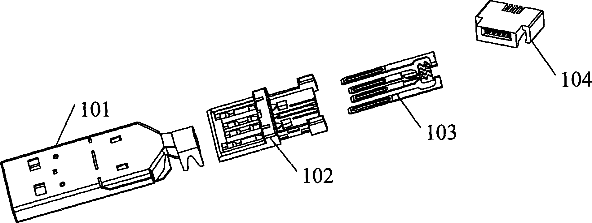
图1为本实用新型实施例提供的连接器的结构分解图;Figure 1 is an exploded view of the structure of the connector provided by the embodiment of the present invention;
图2为本实用新型实施例提供的连接器的装配图;Figure 2 is an assembly diagram of the connector provided by the embodiment of the present invention;
图3为本实用新型实施例提供的连接器的装配应用图。Fig. 3 is an assembly application diagram of the connector provided by the embodiment of the present invention.
具体实施方式 Detailed ways
为了更好的理解本实用新型的技术方案,下面结合附图详细描述本实用新型提供的实施例。In order to better understand the technical solution of the utility model, the embodiments provided by the utility model will be described in detail below in conjunction with the accompanying drawings.
本实用新型实施例提供一种USB A TYPE公头刺破式连接器,如图1、图2和图3所示,该连接器包括:主体铁壳101、主体胶芯102、导体端子103和塑胶后盖104,该主体胶芯102的头部具有接触片,用于插接在其他的电子设备的接口中,所述主体铁壳101套在所述主体胶芯102的头部,所述导体端子103插入所述主体胶芯102的卡槽中,所述后盖104套入主体胶芯102的尾部、并将所述导体端子103盖在所述主体胶芯102内,所述后盖105的尾部设置有用于插入芯线的线孔,所述后盖104的两侧设置有第一卡点,所述主体胶芯102的两侧设置有第二卡点,所述第一卡点卡在所述第二卡点上,使主体胶芯102固定不动,所述导体端子103的尾部设置有锥形的尖点。The embodiment of the utility model provides a USB A TYPE male piercing connector, as shown in Figure 1, Figure 2 and Figure 3, the connector includes: a main body iron shell 101, a main body rubber core 102, a conductor terminal 103 and Plastic back cover 104, the head of the main body rubber core 102 has a contact piece for plugging into the interface of other electronic equipment, the main body iron shell 101 is sleeved on the head of the main body rubber core 102, the The conductor terminal 103 is inserted into the card slot of the main body rubber core 102, the rear cover 104 is inserted into the tail of the main body rubber core 102, and the conductor terminal 103 is covered in the main body rubber core 102, the back cover The tail portion of 105 is provided with a wire hole for inserting a core wire, first clamping points are provided on both sides of the rear cover 104, second clamping points are provided on both sides of the main body rubber core 102, and the first clamping points Clamped on the second clamping point, the main body rubber core 102 is fixed, and the tail of the conductor terminal 103 is provided with a tapered sharp point.
将四根芯线插入后盖104的四个孔,然后将后盖104下压,后盖104的两侧的第一卡点卡住主体胶芯102的第二卡点使之固定不动,导体端子103尾部设有的两个锥型的尖点用于刺破线缆芯线的外皮使之与芯线里面的铜丝接触形成导通。Insert the four core wires into the four holes of the back cover 104, and then press down the back cover 104, the first clamping points on both sides of the rear cover 104 clamp the second clamping points of the main rubber core 102 to keep it fixed, The two tapered sharp points provided at the tail of the conductor terminal 103 are used to pierce the sheath of the cable core wire to make contact with the copper wire inside the core wire to form conduction.
该连接器只需将线缆的四根芯线穿进孔里面然后压一次就完成,加工简单,且能实现用自动化来生产,生产成本大大降低。且不需要专业的工具来压入,作业方式简单,只要将芯线穿入线孔中然后向下压入后盖就完成了导通,无需焊接,不会产生有害汽体,对环境无污染,连接器与线缆的连接更可靠,避免了人工焊接工艺所带来的种种品质不良,另外双刺破尖点保证连接器与线缆的接触是双保险。The connector only needs to pass the four core wires of the cable into the hole and then press it once to complete, the processing is simple, and it can be produced by automation, and the production cost is greatly reduced. It does not require professional tools to press in, and the operation method is simple, as long as the core wire is inserted into the wire hole and then pressed down into the back cover to complete the conduction, no welding is required, no harmful gas will be produced, and there is no pollution to the environment , The connection between the connector and the cable is more reliable, avoiding various poor quality caused by the manual welding process, and the double puncture points ensure that the contact between the connector and the cable is double insurance.
以上对本实用新型实施例所提供的一种USB A TYPE公头连接器进行了详细介绍,对于本领域的一般技术人员,依据本实用新型实施例的思想,在具体实施方式及应用范围上均会有改变之处,综上所述,本说明书内容不应理解为对本实用新型的限制。A USB A TYPE male connector provided by the embodiment of the utility model has been introduced in detail above. For those of ordinary skill in the art, according to the idea of the embodiment of the utility model, both the specific implementation and the scope of application will be There are changes, and in summary, the content of this specification should not be construed as limiting the utility model.
Claims (1)
Priority Applications (1)
| Application Number | Priority Date | Filing Date | Title |
|---|---|---|---|
| CN2012200727845U CN202454802U (en) | 2012-02-29 | 2012-02-29 | Universal serial bus (USB) A TYPE male connector |
Applications Claiming Priority (1)
| Application Number | Priority Date | Filing Date | Title |
|---|---|---|---|
| CN2012200727845U CN202454802U (en) | 2012-02-29 | 2012-02-29 | Universal serial bus (USB) A TYPE male connector |
Publications (1)
| Publication Number | Publication Date |
|---|---|
| CN202454802U true CN202454802U (en) | 2012-09-26 |
Family
ID=46870632
Family Applications (1)
| Application Number | Title | Priority Date | Filing Date |
|---|---|---|---|
| CN2012200727845U Expired - Fee Related CN202454802U (en) | 2012-02-29 | 2012-02-29 | Universal serial bus (USB) A TYPE male connector |
Country Status (1)
| Country | Link |
|---|---|
| CN (1) | CN202454802U (en) |
Cited By (1)
| Publication number | Priority date | Publication date | Assignee | Title |
|---|---|---|---|---|
| CN109980422A (en) * | 2019-04-09 | 2019-07-05 | 永新县荣合成电子科技有限公司 | Two core A public affairs USB charging cables of one kind and preparation method |
-
2012
- 2012-02-29 CN CN2012200727845U patent/CN202454802U/en not_active Expired - Fee Related
Cited By (1)
| Publication number | Priority date | Publication date | Assignee | Title |
|---|---|---|---|---|
| CN109980422A (en) * | 2019-04-09 | 2019-07-05 | 永新县荣合成电子科技有限公司 | Two core A public affairs USB charging cables of one kind and preparation method |
Similar Documents
| Publication | Publication Date | Title |
|---|---|---|
| CN104158044B (en) | A kind of manufacturing process of USB connector | |
| CN201369400Y (en) | Exempt from DB first connector terminal of type of welding | |
| CN202454803U (en) | MICRO universal serial bus (USB) piercing type plug connector | |
| CN204330841U (en) | A kind of electric energy meter terminating wire locking device | |
| CN204304024U (en) | a cable connector | |
| CN201340907Y (en) | Terminal group of electric connector | |
| CN201378637Y (en) | Welding-free plug connector | |
| CN203895625U (en) | Bare wire automatic butt-joint pipe | |
| CN203635811U (en) | Automobile wire harness bending device | |
| CN205543304U (en) | Wire -terminal with from function of skinning | |
| CN207098259U (en) | A kind of cable stripping tool with heating function | |
| CN203423334U (en) | MICRO USB male header with printed circuit board | |
| CN201075404Y (en) | Puncture type DVI interface | |
| CN205081164U (en) | Positive negative pole is with soft packet of cylinder battery and battery terminal of end | |
| CN203761167U (en) | Outgoing line assembly of compressor stator | |
| CN203288795U (en) | New MICRO USB piercing electrical connector | |
| CN202308523U (en) | Improved structure of anti-electromagnetic interference connector | |
| CN203932399U (en) | A connector terminal and battery conductive connector | |
| CN205159578U (en) | Welding crimping hybrid USB terminal | |
| CN222261386U (en) | Piercing FFC Connector | |
| CN204271274U (en) | Multifunctional fish mouth presss from both sides | |
| CN203944965U (en) | The electric iron base of being convenient to the welding of 2M wire jumper and detecting | |
| CN204464517U (en) | Ot terminal connector | |
| CN104362440A (en) | Multifunctional fish mouth clamp | |
| CN203813083U (en) | Wire clamping type SATA connector |
Legal Events
| Date | Code | Title | Description |
|---|---|---|---|
| C14 | Grant of patent or utility model | ||
| GR01 | Patent grant | ||
| C17 | Cessation of patent right | ||
| CF01 | Termination of patent right due to non-payment of annual fee | ||
| CF01 | Termination of patent right due to non-payment of annual fee |
Granted publication date: 20120926 Termination date: 20140229 |