CN202448017U - Polishing machine - Google Patents
Polishing machine Download PDFInfo
- Publication number
- CN202448017U CN202448017U CN2011204641868U CN201120464186U CN202448017U CN 202448017 U CN202448017 U CN 202448017U CN 2011204641868 U CN2011204641868 U CN 2011204641868U CN 201120464186 U CN201120464186 U CN 201120464186U CN 202448017 U CN202448017 U CN 202448017U
- Authority
- CN
- China
- Prior art keywords
- polishing
- transmission mechanism
- polishing machine
- casing
- driving mechanism
- Prior art date
- Legal status (The legal status is an assumption and is not a legal conclusion. Google has not performed a legal analysis and makes no representation as to the accuracy of the status listed.)
- Expired - Fee Related
Links
Images
Abstract
The utility model discloses a polishing machine, comprising a polishing mechanism and a transmission mechanism connected with the polishing mechanism; a driving mechanism is connected below the transmission mechanism; the polishing mechanism comprises an upper polishing plate and a lower polishing plate; the transmission mechanism comprises a supporting shaft for supporting the lower polishing plate, and a moving device arranged on the periphery of the supporting shaft and connected with the driving mechanism; a reducer is connected between the driving mechanism and the transmission mechanism; and a box body is arranged out of the driving mechanism and the transmission mechanism. The polishing machine is long in service life and high in polishing precision. The transmission device connected with the driving device is provided with the reducer, so that the transmission mechanism is high in power, good in stability, and more durable.
Description
Technical field
The utility model relates to the polishing machine mechanical field, is specifically related to a kind of polishing machine.
Background technology
The kind of conventional polisher is a lot; We mainly introduce the large-scale automatic numerical control polishing machine that is used for polished glass, pottery etc., are polishing mechanisms above this polishing machine is general, are provided with transmission mechanism below; What conventional polisher was used is cycloidal-pin wheel, little, the poor stability of power.What established the support axis axle sleeve of polishing machine outside is self-lubricating bearing, the self-lubricating bearing poor rigidity, is not durable.Transmission mechanism outside casing is that employing is enclosed, is difficult for the working condition of observation transmission mechanism, also is not easy to the dismounting and the loading of transmission mechanism.
The utility model content
The utility model purpose: the utility model provides the polishing machine of a kind of good stability, long service life in order to solve the deficiency of prior art.
Technical scheme: a kind of polishing machine; Comprise polishing mechanism, the transmission mechanism that links to each other with said polishing mechanism; Be connected with driving mechanism below the said transmission mechanism, said polishing mechanism comprises that polished silicon wafer and following polished silicon wafer, said transmission mechanism comprise the back shaft that supports said polished silicon wafer down and be installed in said back shaft and the running gear that links to each other with said driving mechanism on every side; Be connected with decelerator between said driving mechanism and the said transmission mechanism, said driving mechanism and transmission mechanism outside are provided with casing.
As optimization, said back shaft axle sleeve outside is provided with needle bearing.Reduced the fit clearance between bearing and the axle sleeve, the needle bearing good rigidly of changing simultaneously, durable, not easy to wear, service life of having increased polishing machine.
As optimization, the side of said casing is provided with door, and said door is a lower frame with the base, side of said casing, is provided with the fractionation jockey between the side of said casing and the said casing.The lower frame of door adopts detachable apparatus, is come in the casing side, is convenient to the installation and the maintenance of transmission mechanism in the casing.
As optimization, said driving mechanism is a motor, and said motor adopts the industrial computer centralized Control.By the industrial computer centralized Control, intelligent strong.
Beneficial effect: the utility model polishing machine long service life, high efficiency, polishing accuracy height.With transmission device that drive unit links to each other on reductor is housed, make that this transmission mechanism power is big, good stability, more durable.
Description of drawings
Fig. 1 is the utility model polishing machine front view;
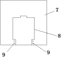
Fig. 2 is side structure sketch map of the big casing of the large-scale polishing machine of the utility model.
The specific embodiment
As shown in the figure; A kind of polishing machine, comprise polishing mechanism 1, with the transmission mechanism 2 that said polishing mechanism 1 links to each other, be connected with driving mechanism 3 below the said transmission mechanism 2; Said polishing mechanism 1 comprises polished silicon wafer and following polished silicon wafer 4; Around said transmission mechanism 2 comprises the back shaft 5 that supports said polished silicon wafer 4 down and is installed in said back shaft 5 and the running gear that links to each other with said driving mechanism 3, be connected with decelerator 6 between said driving mechanism 3 and the said transmission mechanism 2, said driving mechanism 3 and transmission mechanism 2 outsides are provided with casing 7; Said back shaft 5 axle sleeves outside is provided with needle bearing; The side of said casing 7 is provided with door 8, and said door 8 bases, side with said casing 7 are lower frame, is provided with between the side of said casing 7 and the said casing 7 and splits jockey 9; Said driving mechanism 3 is a motor, and said motor adopts the industrial computer centralized Control.
Claims (5)
1. polishing machine; It is characterized in that: comprise polishing mechanism (1), the transmission mechanism (2) that links to each other with said polishing mechanism (1); Be connected with driving mechanism (3) below the said transmission mechanism (2); Said polishing mechanism (1) comprises polished silicon wafer and following polished silicon wafer (4); Said transmission mechanism (2) comprises the back shaft (5) that supports said polished silicon wafer (4) down and is installed in said back shaft (5) and the running gear that links to each other with said driving mechanism (3) on every side, is connected with decelerator (6) between said driving mechanism (3) and the said transmission mechanism (2), is provided with casing (7) outside said driving mechanism (3) and the transmission mechanism (2).
2. according to the said polishing machine of claim 1, it is characterized in that: said back shaft (5) axle sleeve outside is provided with needle bearing.
3. according to the said polishing machine of claim 1; It is characterized in that: the side of said casing (7) is provided with door (8); Said door (8) is a lower frame with the base, side of said casing (7), is provided with between the side of said casing (7) and the said casing (7) to split jockey (9).
4. according to the said polishing machine of claim 1, it is characterized in that: said driving mechanism (3) is a motor.
5. according to the said polishing machine of claim 4, it is characterized in that: said motor adopts the industrial computer centralized Control.
Priority Applications (1)
| Application Number | Priority Date | Filing Date | Title |
|---|---|---|---|
| CN2011204641868U CN202448017U (en) | 2011-11-21 | 2011-11-21 | Polishing machine |
Applications Claiming Priority (1)
| Application Number | Priority Date | Filing Date | Title |
|---|---|---|---|
| CN2011204641868U CN202448017U (en) | 2011-11-21 | 2011-11-21 | Polishing machine |
Publications (1)
| Publication Number | Publication Date |
|---|---|
| CN202448017U true CN202448017U (en) | 2012-09-26 |
Family
ID=46863910
Family Applications (1)
| Application Number | Title | Priority Date | Filing Date |
|---|---|---|---|
| CN2011204641868U Expired - Fee Related CN202448017U (en) | 2011-11-21 | 2011-11-21 | Polishing machine |
Country Status (1)
| Country | Link |
|---|---|
| CN (1) | CN202448017U (en) |
Cited By (1)
| Publication number | Priority date | Publication date | Assignee | Title |
|---|---|---|---|---|
| CN104526523A (en) * | 2014-12-05 | 2015-04-22 | 安徽尧龙竹木制品有限公司 | Inserting type continuous polishing device for board |
-
2011
- 2011-11-21 CN CN2011204641868U patent/CN202448017U/en not_active Expired - Fee Related
Cited By (1)
| Publication number | Priority date | Publication date | Assignee | Title |
|---|---|---|---|---|
| CN104526523A (en) * | 2014-12-05 | 2015-04-22 | 安徽尧龙竹木制品有限公司 | Inserting type continuous polishing device for board |
Similar Documents
| Publication | Publication Date | Title |
|---|---|---|
| CN203636098U (en) | Efficient diamond saw blade base body polisher | |
| CN202448017U (en) | Polishing machine | |
| CN102441834A (en) | Polishing machine | |
| CN202507156U (en) | Large polishing machine | |
| CN206084712U (en) | Plane polishing equipment | |
| CN202738500U (en) | Shaking bed for producing liquid strains | |
| CN102398206A (en) | Grinder | |
| CN201997914U (en) | Automatic material picking mechanism on automatic assembly device | |
| CN201385947Y (en) | Rotary apparatus | |
| CN102441836A (en) | Large-size polishing machine | |
| CN105197639A (en) | Slitter edge winding machine for bag making machine | |
| CN202399138U (en) | Transmission mechanism of polishing machine | |
| CN202063511U (en) | Transmission device for disc feeder | |
| CN202448025U (en) | Grinding machine | |
| CN202037519U (en) | Novel terrazzo machine | |
| CN202388383U (en) | Transmission mechanism of polishing machine | |
| CN202726709U (en) | Grinding machine | |
| CN202780790U (en) | Lathe polishing machine | |
| CN203566080U (en) | Lifting platform device for laser engraving machine | |
| CN202082355U (en) | Chain transmission mechanism for chain-type steel pulling machine | |
| CN202952139U (en) | Hub polishing unit | |
| CN201960434U (en) | Rough grinding machine | |
| CN205309745U (en) | Automatic lock screw equipment | |
| CN203428436U (en) | Dividing transmission positioning device | |
| CN202388380U (en) | Box for transmission mechanism of polishing machine |
Legal Events
| Date | Code | Title | Description |
|---|---|---|---|
| C14 | Grant of patent or utility model | ||
| GR01 | Patent grant | ||
| CF01 | Termination of patent right due to non-payment of annual fee |
Granted publication date: 20120926 Termination date: 20141121 |
|
| EXPY | Termination of patent right or utility model |