CN202427697U - Device for steam removal in curing barn during chemical dye production - Google Patents
Device for steam removal in curing barn during chemical dye production Download PDFInfo
- Publication number
- CN202427697U CN202427697U CN2011205400553U CN201120540055U CN202427697U CN 202427697 U CN202427697 U CN 202427697U CN 2011205400553 U CN2011205400553 U CN 2011205400553U CN 201120540055 U CN201120540055 U CN 201120540055U CN 202427697 U CN202427697 U CN 202427697U
- Authority
- CN
- China
- Prior art keywords
- recovery
- utility
- model
- chemical dye
- production
- Prior art date
- Legal status (The legal status is an assumption and is not a legal conclusion. Google has not performed a legal analysis and makes no representation as to the accuracy of the status listed.)
- Expired - Fee Related
Links
Images
Abstract
The utility model relates to a device for steam removal in a curing barn during the chemical dye production. The device comprises a main recovery pipeline, branch recovery pipelines, exhaust inlets and a recovery tower. The device is characterized in that the branch recovery pipelines communicated with the main recovery pipeline are uniformly arranged on the main recovery pipeline at intervals; each exhaust inlet is correspondingly formed under each branch recovery pipeline; one end of the main recovery pipeline is connected with the recovery tower through an arranged induced draft fan; and the induced draft fan is provided with a frequency converter. According to the utility model, a work point induced air force is provided through the arranged induced draft fan to increase the quantity of the discharged steam in the curing barn and then facilitate the dust removal effect of the work point in the process of the chemical dye production; and an energy-saving heating device used for chemical dye reaction is extremely remarkable in energy conservation and consumption reduction. The device disclosed by the utility model can effectively improve the production efficiency and quality, can ensure safety production and avoids economic loss, and is simple in structure, reasonable in design, safe and reliable in quality and extremely remarkable in application effect.
Description
Technical field
The utility model relates to a kind of humidity-discharging device, the barn steam humidity-discharging device during particularly a kind of chemical dyestuff is produced.
Background technology
At present, barn steam hydrofuge is generally the nature discharging in the chemical dyestuff production process, so both has been unfavorable for environmental protection, can influence the raising of production efficiency and product quality again.
Therefore, the barn steam humidity-discharging device of the significant chemical dyestuff of a kind of simple in structure, reasonable in design, safe and reliable, energy-saving and cost-reducing, practical function in producing is provided, becomes one of these those skilled in the art problem anxious to be addressed.
The utility model content
The purpose of the utility model is to overcome above-mentioned weak point, and the barn steam humidity-discharging device of the significant chemical dyestuff of a kind of simple in structure, reasonable in design, safe and reliable, energy-saving and cost-reducing, practical function in producing is provided.
For realizing that the technical scheme that above-mentioned purpose the utility model is adopted is: the barn steam humidity-discharging device during a kind of chemical dyestuff is produced, this device comprise the recovery trunk line, reclaim branch pipe(tube), inlet scoop and recovery tower; It is characterized in that on the said recovery trunk line evenly being provided with at interval the recovery branch pipe(tube) with its UNICOM, each reclaims branch pipe(tube) below correspondence and is provided with the inlet scoop; Said recovery trunk line one end is connected with recovery tower through the air-introduced machine that is provided with.
The beneficial effect of the utility model is: the utility model is in the chemical dyestuff production process; Provide operating point air inducing power to increase discharging barn quantity of steam through the air-introduced machine that is provided with; The hydrofuge effect that helps its operating point; The energy-saving heating device that is used for the chemical dyestuff reaction, the energy conservation and consumption reduction effects highly significant.The utility model is effectively enhanced productivity and quality, guarantees safety in production.It is simple in structure, and is reasonable in design, and performance is safe and reliable, obvious application effect.
Description of drawings
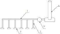
Fig. 1 is the utility model structural representation.
Among the figure: 1 reclaims trunk line, and 2 reclaim branch pipe(tube), 3 inlet scoops, 4 recovery towers, 5 air-introduced machines.
The specific embodiment
Below in conjunction with accompanying drawing and preferred embodiment, details are as follows to the specific embodiment, structure, the characteristic that provide according to the utility model:
Referring to Fig. 1, the barn steam humidity-discharging device during a kind of chemical dyestuff is produced, this device comprise recovery trunk line 1, reclaim branch pipe(tube) 2, inlet scoop 3 and recovery tower 4; Evenly be provided with at interval the recovery branch pipe(tube) 2 with its UNICOM on the said recovery trunk line 1, each reclaims branch pipe(tube) 2 below correspondences and is provided with inlet scoop 3; Said recovery trunk line 1 one ends are connected with recovery tower 4 through the air-introduced machine 5 that is provided with.
Said air-introduced machine 5 sets frequency converter.
The utility model is that DYE PRODUCTION provides the barn steam humidity-discharging device in a kind of chemical dyestuff production, is widely used the practical function highly significant.
Above-mentioned with reference to embodiment to the detailed description that the barn steam humidity-discharging device in this chemical dyestuff production carries out, be illustrative rather than determinate; Therefore in the variation and the modification that do not break away under the utility model general plotting, should belong within the protection domain of the utility model.
Claims (2)
1. the barn steam humidity-discharging device during a chemical dyestuff is produced, this device comprise the recovery trunk line, reclaim branch pipe(tube), inlet scoop and recovery tower; It is characterized in that on the said recovery trunk line evenly being provided with at interval the recovery branch pipe(tube) with its UNICOM, each reclaims branch pipe(tube) below correspondence and is provided with the inlet scoop; Said recovery trunk line one end is connected with recovery tower through the air-introduced machine that is provided with.
2. the barn steam humidity-discharging device during chemical dyestuff according to claim 1 is produced is characterized in that said air-introduced machine sets frequency converter.
Priority Applications (1)
| Application Number | Priority Date | Filing Date | Title |
|---|---|---|---|
| CN2011205400553U CN202427697U (en) | 2011-12-21 | 2011-12-21 | Device for steam removal in curing barn during chemical dye production |
Applications Claiming Priority (1)
| Application Number | Priority Date | Filing Date | Title |
|---|---|---|---|
| CN2011205400553U CN202427697U (en) | 2011-12-21 | 2011-12-21 | Device for steam removal in curing barn during chemical dye production |
Publications (1)
| Publication Number | Publication Date |
|---|---|
| CN202427697U true CN202427697U (en) | 2012-09-12 |
Family
ID=46777172
Family Applications (1)
| Application Number | Title | Priority Date | Filing Date |
|---|---|---|---|
| CN2011205400553U Expired - Fee Related CN202427697U (en) | 2011-12-21 | 2011-12-21 | Device for steam removal in curing barn during chemical dye production |
Country Status (1)
| Country | Link |
|---|---|
| CN (1) | CN202427697U (en) |
Cited By (1)
| Publication number | Priority date | Publication date | Assignee | Title |
|---|---|---|---|---|
| CN104709716A (en) * | 2015-03-11 | 2015-06-17 | 张家港市双龙氧化锌厂 | High-temperature powder conveying and guiding-out device |
-
2011
- 2011-12-21 CN CN2011205400553U patent/CN202427697U/en not_active Expired - Fee Related
Cited By (1)
| Publication number | Priority date | Publication date | Assignee | Title |
|---|---|---|---|---|
| CN104709716A (en) * | 2015-03-11 | 2015-06-17 | 张家港市双龙氧化锌厂 | High-temperature powder conveying and guiding-out device |
Similar Documents
| Publication | Publication Date | Title |
|---|---|---|
| CN202427697U (en) | Device for steam removal in curing barn during chemical dye production | |
| CN203048907U (en) | Device for methyl esterification and continuous methanol purification of biodiesel | |
| CN202638465U (en) | Negative pressure rice bran settling device for processing rice | |
| CN203116487U (en) | Waste-heat utilization drying kiln | |
| CN205570006U (en) | Digester environmental protection dust collector | |
| CN202648354U (en) | High-temperature heat pump energy saving system of industrial rotary drum drying machine | |
| CN201917191U (en) | Device used for drying bamboo building template raw materials | |
| CN205066478U (en) | Energy -concerving and environment -protective kiln of no chimney minimum discharge | |
| CN204268881U (en) | A kind of novel aluminum scrap recovery furnace device | |
| CN201999744U (en) | Solar-wind power complementation sea salt drying machine | |
| CN202349990U (en) | Medicine adding system used for cement dual-pressure waste heat power station | |
| CN214577249U (en) | Exhaust steam waste heat and excess pressure utilization device | |
| CN204039309U (en) | Waste-heat recovery device in a kind of Vltra tears production system | |
| CN202770236U (en) | Kiln afterheat recycling device | |
| CN202432877U (en) | Curing barn tail gas thermal energy recovery system for chemical dyestuff production | |
| CN202902808U (en) | Tail-gas-preheated drum drying device for chemical fiber production | |
| CN202442321U (en) | Equipment for producing overheated steam by virtue of circulating water | |
| CN202756255U (en) | Slurry pump with fan | |
| CN201978880U (en) | Externally-coated functional film drying device | |
| CN201867082U (en) | Device for realizing comprehensive utilization of residual heat of solar ultra clear glass melting furnace | |
| CN202248053U (en) | Monomer recovery condensed water recycling device | |
| CN202630628U (en) | Fishing net drying device | |
| CN201414395Y (en) | Sesame baking and stirring machine having residual heat utilization apparatus | |
| CN201628449U (en) | Radiofrequency drying machine with cooling water recycling device | |
| CN204043303U (en) | A kind of drying device of secondary settlement |
Legal Events
| Date | Code | Title | Description |
|---|---|---|---|
| C14 | Grant of patent or utility model | ||
| GR01 | Patent grant | ||
| CF01 | Termination of patent right due to non-payment of annual fee |
Granted publication date: 20120912 Termination date: 20151221 |
|
| EXPY | Termination of patent right or utility model |