CN202414179U - Dust-free storage tank - Google Patents
Dust-free storage tank Download PDFInfo
- Publication number
- CN202414179U CN202414179U CN 201220048158 CN201220048158U CN202414179U CN 202414179 U CN202414179 U CN 202414179U CN 201220048158 CN201220048158 CN 201220048158 CN 201220048158 U CN201220048158 U CN 201220048158U CN 202414179 U CN202414179 U CN 202414179U
- Authority
- CN
- China
- Prior art keywords
- tank body
- tank
- storage tank
- dust
- discharging opening
- Prior art date
- Legal status (The legal status is an assumption and is not a legal conclusion. Google has not performed a legal analysis and makes no representation as to the accuracy of the status listed.)
- Expired - Fee Related
Links
Images
Landscapes
- Filtering Of Dispersed Particles In Gases (AREA)
Abstract
The utility model provides a dust-free storage tank used in dry activation production of light calcium carbonate. The dust-free storage tank comprises a tank body, wherein the top part of the tank body is provided with a feeding hole; a helical conveyer which is inclined upwards is arranged between the bottom of the tank body and a discharging hole; the upper end of the tank body is communicated with a buffer tank; and a return pipe communicated with the tank body is arranged at the discharging hole of the tank body. The dust-free storage tank provided by the utility model is simple in structure and convenient in operations; the conventional storage tank is modified, and the buffer tank and the return pipe are additionally arranged on the storage tank, so that gas in the tank body does not overflow to bring out ultrafine particles and cause dust pollutions to air in the feeding and discharging procedures of the storage tank.
Description
Technical field
The utility model relates to a kind of storage equipment in the precipitated calcium carbonate dry activation is produced, especially a kind of no airborne dust storage tank.
Background technology
In existing precipitated calcium carbonate dry activation was produced, the calcene (hereinafter to be referred as calcium activated) that obtains after activated was stored in earlier in the storage tank, calcium activated is divided in the required packaging bag again; But; Owing to when packing, have the slit between the discharging opening of storage tank and packaging bag, therefore when calcium activated flowed into packaging bag, the interior gas of bag can carry the calcium activated dust and between the slit of sack, overflow; Produce airborne dust, cause aerial contamination.
The utility model content
The technical matters that the utility model will solve provides and a kind ofly can reduce the storage tank that air-polluting does not have airborne dust.
For solving the problems of the technologies described above, the technical scheme that the utility model is taked is: a kind of no airborne dust storage tank, comprise tank body, and the top of tank body is provided with inlet point, is provided with acclivitous auger loader between the bottom of tank body and the discharging opening; Its key is: the upper end of tank body is connected with expansion tank, and the discharging opening place of tank body is provided with the counter flow pipe that is communicated with tank body.
Be provided with the check valve that gas is flowed to expansion tank from tank body in above-mentioned tank body and the pipeline that expansion tank is connected.
The top of above-mentioned expansion tank is ultra-fine filter cloth.
Above-mentioned counter flow pipe is located at the outside of discharging opening, its bottom and discharging opening and together, the other end is connected with the tank body upper end, be provided with in the reflux line make gas from counter flow pipe to the mobile check valve of tank body.
Adopt the beneficial effect that technique scheme produced to be: the utility model is simple in structure, and is easy to operate, and original storage tank is improved, and on storage tank, set up expansion tank and counter flow pipe, eliminated the dust pollution that in charging, discharging process, causes.When in tank body, importing material by inlet point, the tank body internal pressure increases, the check valve SELF CL of counter flow pipe; The check valve that is communicated with expansion tank is opened automatically, and gas flows into expansion tank, again through ultra-fine filter cloth exhaust to atmosphere; And the dust that carries in the gas filtered, avoided dust pollution; When starting the auger loader discharging, the tank body internal pressure reduces, and is communicated with the check valve SELF CL of expansion tank, and the check valve of counter flow pipe is opened automatically, and the gas of accepting in the packaging bag of material is flowed in the tank body by counter flow pipe automatically, has avoided dust pollution.
Description of drawings
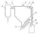
Fig. 1 is the structural representation of the utility model;
Among the figure, 1, tank body, 2, expansion tank, 3, auger loader, 4, counter flow pipe, 5, inlet point, 6, discharging opening, 7, check valve, 8, ultra-fine filter cloth, 9, check valve, 10, packaging bag.
The specific embodiment
Below in conjunction with the accompanying drawing and the specific embodiment the utility model is done further detailed explanation.
Be illustrated in figure 1 as the structural representation of the utility model.Be provided with acclivitous auger loader 3 between the bottom of the tank body 1 of the utility model and the discharging opening 6, the bottom of tank body 1 is connected with the top of auger loader 3, and the end of auger loader 3 is connected with discharging opening 6; The upper end of tank body 1 is connected with expansion tank 2; In the pipeline that is communicated with the two, be provided with check valve 7; Check valve 7 makes gas to flow to expansion tank 2 from tank body 1; The top of expansion tank 2 is ultra-fine filter cloth 8, and ultra-fine filter cloth 8 makes the gas exhaust to atmosphere in the expansion tank 2, and the dust that carries in the gas is filtered; Discharging opening 6 places of tank body 1 are provided with the counter flow pipe 4 that is communicated with tank body 1.Counter flow pipe 4 is located at the outside of discharging opening 6, its bottom and discharging opening 6 and together, the other end is connected with tank body 1 upper end, be provided with in the reflux line make gas from counter flow pipe 4 to the mobile check valve 9 of tank body 1.
When charging, check valve 9 is closed, and check valve 7 is opened, and the gas in the tank body 1 gets in the expansion tank 2, and through ultra-fine filter cloth 8 exhaust to atmospheres, the dust that carries in the gas is trapped in the expansion tank 2 again, produces airborne dust when having avoided charging; When discharging, check valve 7 is closed, and check valve 9 is opened, and the gas in the packaging bag 10 gets in the tank body 1 through counter flow pipe 4, produces airborne dust when having avoided discharging.
Claims (4)
1. a no airborne dust storage tank comprises tank body (1), and the top of tank body (1) is provided with inlet point (5), is provided with acclivitous auger loader (3) between the bottom of tank body (1) and the discharging opening (6); It is characterized in that: the upper end of tank body (1) is connected with expansion tank (2), and the discharging opening (6) of tank body (1) locates to be provided with the counter flow pipe (4) that is communicated with tank body (1).
2. a kind of no airborne dust storage tank according to claim 1 is characterized in that: be provided with the check valve (7) that gas is flowed to expansion tank (2) from tank body (1) in said tank body (1) and the pipeline that expansion tank (2) is connected.
3. a kind of no airborne dust storage tank according to claim 1 is characterized in that: the top of said expansion tank (2) is ultra-fine filter cloth (8).
4. a kind of no airborne dust storage tank according to claim 1; It is characterized in that: said counter flow pipe (4) is located at the outside of discharging opening (6); Its bottom and discharging opening (6) are also together; The other end is connected with tank body (1) upper end, is provided with the check valve (9) that gas is flowed to tank body (1) from counter flow pipe (4) in the reflux line.
Priority Applications (1)
| Application Number | Priority Date | Filing Date | Title |
|---|---|---|---|
| CN 201220048158 CN202414179U (en) | 2012-02-15 | 2012-02-15 | Dust-free storage tank |
Applications Claiming Priority (1)
| Application Number | Priority Date | Filing Date | Title |
|---|---|---|---|
| CN 201220048158 CN202414179U (en) | 2012-02-15 | 2012-02-15 | Dust-free storage tank |
Publications (1)
| Publication Number | Publication Date |
|---|---|
| CN202414179U true CN202414179U (en) | 2012-09-05 |
Family
ID=46738966
Family Applications (1)
| Application Number | Title | Priority Date | Filing Date |
|---|---|---|---|
| CN 201220048158 Expired - Fee Related CN202414179U (en) | 2012-02-15 | 2012-02-15 | Dust-free storage tank |
Country Status (1)
| Country | Link |
|---|---|
| CN (1) | CN202414179U (en) |
Cited By (2)
| Publication number | Priority date | Publication date | Assignee | Title |
|---|---|---|---|---|
| CN103043246A (en) * | 2012-12-13 | 2013-04-17 | 芜湖美的厨卫电器制造有限公司 | Automatic feeding mechanism |
| CN105059576A (en) * | 2015-07-31 | 2015-11-18 | 江苏艾特克阻燃材料有限公司 | Vacuum degassing packaging system for inorganic flame retardant powder |
-
2012
- 2012-02-15 CN CN 201220048158 patent/CN202414179U/en not_active Expired - Fee Related
Cited By (3)
| Publication number | Priority date | Publication date | Assignee | Title |
|---|---|---|---|---|
| CN103043246A (en) * | 2012-12-13 | 2013-04-17 | 芜湖美的厨卫电器制造有限公司 | Automatic feeding mechanism |
| CN103043246B (en) * | 2012-12-13 | 2015-01-07 | 芜湖美的厨卫电器制造有限公司 | Automatic feeding mechanism |
| CN105059576A (en) * | 2015-07-31 | 2015-11-18 | 江苏艾特克阻燃材料有限公司 | Vacuum degassing packaging system for inorganic flame retardant powder |
Similar Documents
| Publication | Publication Date | Title |
|---|---|---|
| CN202414179U (en) | Dust-free storage tank | |
| CN206068966U (en) | A kind of vacuum feeder | |
| CN206350959U (en) | A kind of grain and oil processing dust treatment plant | |
| CN202729345U (en) | Pneumatic dedusting system | |
| CN204024699U (en) | Gas drainage pipeline draining deslagging device | |
| CN208250289U (en) | A kind of yeast fermentor containing reclaimed materials liquid device | |
| CN203359578U (en) | Dust removing device of powder storage tank | |
| CN203173840U (en) | Air agitating device of strontium chloride reaction tank | |
| CN204042391U (en) | A kind of filling fluid oil device | |
| CN203696781U (en) | Sand material feeding mechanism | |
| CN202337486U (en) | Sealed transferring device for dry powder of electrolytic copper powder | |
| CN205833118U (en) | A kind of device applying big packaging microsphere sodium hydroxide to produce xanthates | |
| CN204601834U (en) | A kind of built-in dry dust pre-processing device | |
| CN204182587U (en) | A kind of grey sand separator | |
| CN203558371U (en) | Powder material tank | |
| CN203954813U (en) | A kind of ink glue filter vat | |
| CN203475521U (en) | Vacuum suppressor of non-negative-pressure pressure-superposed water supply device | |
| CN202762386U (en) | Sand mixer with exhaust expansion device | |
| CN202226279U (en) | Environment-friendly bulk cement tank | |
| CN211189679U (en) | Tar volatile recovery device | |
| CN202893089U (en) | Bag type dust collector | |
| CN209223375U (en) | A kind of plasma cutting machine dust-proof water tank | |
| CN208441888U (en) | A kind of negative pressure automatic drainage device | |
| CN205816710U (en) | A kind of liquid glass conveyer device | |
| CN204038493U (en) | Air cushion-belt conveyer |
Legal Events
| Date | Code | Title | Description |
|---|---|---|---|
| C14 | Grant of patent or utility model | ||
| GR01 | Patent grant | ||
| C17 | Cessation of patent right | ||
| CF01 | Termination of patent right due to non-payment of annual fee |
Granted publication date: 20120905 Termination date: 20130215 |