CN202410891U - Industrial skid mast - Google Patents
Industrial skid mast Download PDFInfo
- Publication number
- CN202410891U CN202410891U CN2012200141839U CN201220014183U CN202410891U CN 202410891 U CN202410891 U CN 202410891U CN 2012200141839 U CN2012200141839 U CN 2012200141839U CN 201220014183 U CN201220014183 U CN 201220014183U CN 202410891 U CN202410891 U CN 202410891U
- Authority
- CN
- China
- Prior art keywords
- mast
- main body
- hanger
- skid
- industrial
- Prior art date
- Legal status (The legal status is an assumption and is not a legal conclusion. Google has not performed a legal analysis and makes no representation as to the accuracy of the status listed.)
- Expired - Fee Related
Links
Images


Landscapes
- Spray Control Apparatus (AREA)
Abstract
The utility model relates to a tool for industrial spray coating product line and belongs to the field of tools for industrial product lines. The industrial skid mast is characterized in that the industrial skid mast comprises a vertical mast main body, wherein the mast main body is supported by rib plates which are oblique on the lower part in all sides, the mast main body and the rib plates are fixed on a bottom plate at the bottom, and the bottom plate is mounted on a skid; and the mast main body is provided with multiple hanger fixing holes from top to bottom, transverse hanger fixing short rods are mounted in the hanger fixing holes, and coating hangers are fixed on the hanger fixing short rods. According to the industrial skid mast, the mast mounted on the skid is used for fixing hangers, various types of or multiple hangers can be fixed on the mast by the combination of the hanger fixing holes and the hanger fixing short rods at the same time, and furthermore, the hanger fixing holes are arranged on the two sides of the mast main body, so the spray coating tools can be mounted on the two sides, and has better adaptability on the spray coating of various types of workpieces, meanwhile the assembly and disassembly are convenient, the auxiliary working hours can be greatly saved, and the production efficiency is improved.
Description
Technical field
The utility model relates to the instrument on a kind of industrial spray-coating line, specifically, relates to the skid mast that is used for industrial spray-coating line.
Background technology
At present, existing application is that there is weak point in this mode on the brace that directly is fixed on above the bedframe with hanger on the paint line; Be exactly only to be suitable for single variety or paint line of less types, if need to accomplish the spraying of multi-assortment production on the paint line, then the replacing of hanger and adjustment need take a large amount of working times; Have a strong impact on production efficiency; And, also can influence production line, thereby have influence on the coating quality of workpiece because replacing or adjustment hanger need the time.
Summary of the invention
The utility model technical problem to be solved provides a kind of industrial skid mast, and it is poor to solve present industrial application brace versatility, and influences the defective of Workpiece coating quality.
Technical scheme
A kind of industrial skid mast is characterized in that: comprise vertical mast main body, said mast main body supports through the oblique floor in four sides, bottom, and is fixed on the base plate of bottom with floor, and said base plate is installed on the sled.
Be provided with a plurality of hanger fixing holes on the said mast main body from top to bottom, fixedly quarter butt of horizontal hanger is installed in said hanger fixing hole, application is fixed on said hanger fixedly on the quarter butt with hanger.
Said mast main body adopts the stainless steel square pipe to make, and the bottom has spilled water hole.
Said hanger fixing hole is staggered in opposite directions perforate on the relative two sides of said mast main body respectively, has many row's hanger fixing holes from top to bottom.
Said hanger fixedly quarter butt is installed on the two sides of not perforate of said mast main body, is crisscross arranged relatively.
Two masts are installed on the sled, and the base plate of mast is fixed on the sled through screw.
Beneficial effect
The industrial skid mast of the utility model adopts the mast that is installed on the sled to fix hanger, on mast, uses hanger fixing hole and the fixedly cooperation of quarter butt of hanger, can fix multiple or a plurality of hangers simultaneously; And replacing is very convenient; In mast main body both sides the hanger fixing hole is set all, can realizes spraying the frock both sides and install, the both sides height can be adjusted arbitrarily; The adaptability preferably that is coated with to many kinds workpiece; And conveniently assemble and disassemble can be saved a large amount of unproductive times, has improved production efficiency.
Description of drawings
Fig. 1 is the utility model sketch map.
Fig. 2 is the utility model schematic top plan view.
Fig. 3 looks the part cross-sectional schematic for an A-A left side in the utility model.
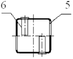
Fig. 4 is the cross-sectional schematic of overlooking of the hanger fixing hole of the utility model middle mast main body.
Fig. 5 is the sketch map that two masts are installed on sled in the utility model.
Wherein: 1-mast main body, the 2-floor, the 3-base plate, the 4-sled, 5-hanger fixing hole, the 6-hanger is quarter butt fixedly, and hanger is used in the 7-application, 8-spilled water hole, 9-screw.
The specific embodiment
Below in conjunction with specific embodiment and accompanying drawing, further set forth the utility model.
In order to enhance productivity, the convenient use with the laws of use of hanger reality on production line, set up a kind of special skid mast according to application, is used to replace present brace.
A kind of industrial skid mast comprises vertical mast main body 1, and said mast main body 1 supports through the oblique floor 2 in four sides, bottom, and is fixed on the base plate 3 of bottom with floor 2, and said base plate 3 is installed on the sled 4.
Be provided with a plurality of hanger fixing holes 5 on the said mast main body 1 from top to bottom, fixedly quarter butt 6 of horizontal hanger is installed in said hanger fixing hole 5, application is fixed on said hanger fixedly on the quarter butt 6 with hanger 7.
Said mast main body 1 adopts the stainless steel square pipe to make, and the bottom has spilled water hole 8, to guarantee that stainless steel square tube inside can residual water.Floor 2 also can use stainless steel or other metal materials to make with base plate 3, and 3 welderings are one to mast main body 1 with base plate through floor 2.Shown in accompanying drawing 1 and accompanying drawing 2.
Said hanger fixing hole 5 is staggered in opposite directions perforate on the relative two sides of said mast main body 1 respectively, has many row's hanger fixing holes 5 from top to bottom, and said hanger fixedly quarter butt 6 is installed on the two sides of not perforate of said mast main body 1, is crisscross arranged relatively.With shown in the accompanying drawing 4, shown the fixedly position of quarter butt 6 settings of hanger fixing hole 5 and hanger from both direction in length and breadth like accompanying drawing 3 respectively.Accompanying drawing 3 show said application with hanger 7 one ends by hanger fixedly quarter butt 6 fix, the other end opened on the mast main body 1 hanger fixing hole 5 block up and down.Accompanying drawing 4 shows the fixedly staggered relatively horizontally set of quarter butt 6 of hanger.
In mast main body 1 both sides hanger fixing hole 5 is arranged all like this, can realize spraying the frock both sides and install, the both sides height can be adjusted arbitrarily, to the adaptability preferably that is coated with of many kinds workpiece, and conveniently assemble and disassemble, can save a large amount of unproductive times.
Two masts are installed on the sled 4, and the base plate 3 of mast is fixed on the sled 4 through screw 9.Can use multiple or a plurality of hangers so simultaneously, can rationally arrange according to the demand of production line.
Claims (6)
1. industrial skid mast; It is characterized in that: comprise vertical mast main body (1); Said mast main body (1) supports through the oblique floor (2) in four sides, bottom, and is fixed on the base plate (3) of bottom with floor (2), and said base plate (3) is installed on the sled (4).
2. industrial skid mast as claimed in claim 1; It is characterized in that: be provided with a plurality of hanger fixing holes (5) on the said mast main body (1) from top to bottom; Fixedly quarter butt (6) of horizontal hanger is installed in said hanger fixing hole (5), and application is fixed on said hanger fixedly on the quarter butt (6) with hanger (7).
3. according to claim 1 or claim 2 industrial skid mast, it is characterized in that: said mast main body (1) adopts the stainless steel square pipe to make, and the bottom has spilled water hole (8).
4. industrial skid mast as claimed in claim 3 is characterized in that: said hanger fixing hole (5) has many row's hanger fixing holes (5) from top to bottom for staggered in opposite directions perforate on the relative two sides of said mast main body (1) respectively.
5. industrial skid mast as claimed in claim 4 is characterized in that: said hanger fixedly quarter butt (6) is installed on the two sides of not perforate of said mast main body (1), is crisscross arranged relatively.
6. industrial skid mast as claimed in claim 1 is characterized in that: two masts are installed on the sled (4), and the base plate of mast (3) is fixed on the sled (4) through screw (9).
Priority Applications (1)
| Application Number | Priority Date | Filing Date | Title |
|---|---|---|---|
| CN2012200141839U CN202410891U (en) | 2012-01-13 | 2012-01-13 | Industrial skid mast |
Applications Claiming Priority (1)
| Application Number | Priority Date | Filing Date | Title |
|---|---|---|---|
| CN2012200141839U CN202410891U (en) | 2012-01-13 | 2012-01-13 | Industrial skid mast |
Publications (1)
| Publication Number | Publication Date |
|---|---|
| CN202410891U true CN202410891U (en) | 2012-09-05 |
Family
ID=46735688
Family Applications (1)
| Application Number | Title | Priority Date | Filing Date |
|---|---|---|---|
| CN2012200141839U Expired - Fee Related CN202410891U (en) | 2012-01-13 | 2012-01-13 | Industrial skid mast |
Country Status (1)
| Country | Link |
|---|---|
| CN (1) | CN202410891U (en) |
-
2012
- 2012-01-13 CN CN2012200141839U patent/CN202410891U/en not_active Expired - Fee Related
Similar Documents
| Publication | Publication Date | Title |
|---|---|---|
| CN204194181U (en) | A kind of compartment paint line | |
| CN104110081B (en) | A kind of assembling factory building wallboard and upright post connection structure | |
| CN203924704U (en) | Aluminum alloy pattern plate system | |
| CN202410891U (en) | Industrial skid mast | |
| CN203508322U (en) | Spray-coating hanger for mud guard of bicycle | |
| CN102074148B (en) | Practical training apparatus | |
| CN104235505A (en) | Solderless folding cable support frame | |
| CN204263119U (en) | A kind of adjustable locating support of bar planting percussion drill | |
| CN203197896U (en) | Workpiece storing frame | |
| CN201865229U (en) | Suspended ceiling reverse support | |
| CN204366557U (en) | A kind of work pieces process fixture | |
| CN204059671U (en) | A kind of assembling factory building wallboard and upright post connection structure | |
| CN204747598U (en) | Location drilling template | |
| CN203711280U (en) | Hanger | |
| CN105401775A (en) | Variable cross-section angle iron for aiding positioning | |
| CN205370072U (en) | Variable cross section assistance -localization real -time angle steel | |
| CN203831391U (en) | Mobile meter reading platform | |
| CN104810776A (en) | Novel welding-free detachable bracket | |
| CN203220993U (en) | Spraying room for all-sided spraying | |
| CN205363687U (en) | Concrete column workshop equipment mould is managed in side | |
| CN203390450U (en) | Tower crane stock single limb positioning leaning die | |
| CN203103763U (en) | Power distributing cabinet | |
| CN202393059U (en) | Guide rail installation rack | |
| CN204001195U (en) | Steel work module | |
| CN204565508U (en) | A kind of grillage rivet welding frock |
Legal Events
| Date | Code | Title | Description |
|---|---|---|---|
| C14 | Grant of patent or utility model | ||
| GR01 | Patent grant | ||
| CF01 | Termination of patent right due to non-payment of annual fee |
Granted publication date: 20120905 Termination date: 20150113 |
|
| EXPY | Termination of patent right or utility model |