CN202405134U - Automatic change-over switch appliance - Google Patents
Automatic change-over switch appliance Download PDFInfo
- Publication number
- CN202405134U CN202405134U CN2012200013012U CN201220001301U CN202405134U CN 202405134 U CN202405134 U CN 202405134U CN 2012200013012 U CN2012200013012 U CN 2012200013012U CN 201220001301 U CN201220001301 U CN 201220001301U CN 202405134 U CN202405134 U CN 202405134U
- Authority
- CN
- China
- Prior art keywords
- power supply
- square shaft
- stand
- commonly used
- connecting rod
- Prior art date
- Legal status (The legal status is an assumption and is not a legal conclusion. Google has not performed a legal analysis and makes no representation as to the accuracy of the status listed.)
- Expired - Lifetime
Links
Images


Landscapes
- Transmission Devices (AREA)
Abstract
The utility model relates to an automatic change-over switch appliance, which comprises a first movable contact drawing device and a second movable contact drawing device, wherein the first movable contact drawing device is used for drawing a normally-used power source N-pole movable contact to be disconnected with a normally-used power source N-pole fixed contact, and the second movable contact drawing device is used for drawing a standby power source N-pole movable contact to be disconnected with a standby power source N-pole fixed contact. The first movable contact drawing device is fixedly connected with a square shaft of a standby power source and rotatably connected with a square shaft of a normally-used power source through a first N-pole connecting rod, and the second movable contact drawing device is fixedly connected with the square shaft of the standby power source and rotatably connected with the square shaft of the normally-used power source through a second N-pole connecting rod. The automatic change-over switch appliance can guarantee the N pole not to be disconnected in the change-over process, so that zero line vacation is eliminated, and cost increasing is avoided. Further, change-over speed is unaffected, and higher appliance performance can be obtained.
Description
Technical field
The utility model relates to a kind of twin-power switch electrical equipment, more particularly, relates to and a kind ofly is used for realizing that electric power system switches to the overlapping conversion automatic transfer switching electric appliance of stand-by power supply process N level from power supply commonly used.
Background technology
At present, on the market duplicate supply N level and other he three grades be same rotating shaft, the phenomenon of soaring in the transfer process; Usually way is that N commonly used, stand-by power supply is fixedly connected; But this can influence conversion speed, and because two power-supply systems are different, can influence terminal circuit down.
The utility model content
The technical problem that the utility model will solve is that the above-mentioned defective to prior art provides a kind of automatic transfer switching electric appliance.
The utility model solves the technical scheme that its technical problem adopted: construct a kind of automatic transfer switching electric appliance, comprise the second moving contact draw-gear that is used to draw the first moving contact draw-gear of said power supply N level moving contact commonly used and power supply N level fixed contact commonly used disconnection and is used to draw said stand-by power supply N level moving contact and the disconnection of stand-by power supply N level fixed contact;
The said first moving contact draw-gear is fixedly connected with said stand-by power supply square shaft; And be rotationally connected through a N level connecting rod and said power supply square shaft commonly used; The said second moving contact draw-gear is fixedly connected with said power supply square shaft commonly used, and is rotationally connected through the 2nd N level connecting rod and said stand-by power supply square shaft.
The described automatic transfer switching electric appliance of the utility model, wherein, the said first moving contact draw-gear comprises the first square shaft rocking bar; The said first square shaft rocking bar, one end is fixedly connected with said stand-by power supply square shaft; One end of the other end and a said N level connecting rod is hinged; Said N level connecting rod one end and the said first square shaft rocking bar are hinged, and the other end can be connected with said power supply square shaft commonly used around said power supply square shaft commonly used with rotating freely.
The described automatic transfer switching electric appliance of the utility model, wherein, the said first square shaft rocking bar, one end is provided with and is used for the square opening that cooperates with said stand-by power supply square shaft, and the said first square shaft rocking bar is fixed on the said stand-by power supply square shaft through said square opening.
The described automatic transfer switching electric appliance of the utility model, wherein, the other end of a said N level connecting rod can be connected with said power supply square shaft commonly used around said power supply square shaft commonly used through first axle sleeve with rotating freely;
Said first axle sleeve, one end and said power supply square shaft commonly used are rotationally connected, and hinged with an end of a said N level connecting rod.
The described automatic transfer switching electric appliance of the utility model, wherein, the other end of said first axle sleeve is hinged through first connecting rod and said power supply N level moving contact commonly used, and said first axle sleeve and the hinged position of said first connecting rod also are provided with torsion spring.
The described automatic transfer switching electric appliance of the utility model, wherein, the said second moving contact draw-gear comprises the second square shaft rocking bar; The said second square shaft rocking bar, one end is fixedly connected with said power supply square shaft commonly used; One end of the other end and said the 2nd N level connecting rod is hinged; Said the 2nd N level connecting rod one end and the said second square shaft rocking bar are hinged, and the other end can be connected with said stand-by power supply square shaft around said stand-by power supply square shaft with rotating freely.
The described automatic transfer switching electric appliance of the utility model, wherein, the said second square shaft rocking bar, one end is provided with and is used for the square opening that is connected with said power supply square shaft commonly used, and the said second square shaft rocking bar is fixed on the said power supply square shaft commonly used through said square opening.
The described automatic transfer switching electric appliance of the utility model, wherein, the other end of said the 2nd N level connecting rod can be connected with said stand-by power supply square shaft around said stand-by power supply square shaft through second axle sleeve with rotating freely;
Said second axle sleeve, one end and said stand-by power supply square shaft are rotationally connected, and hinged with an end of said the 2nd N level connecting rod.
The described automatic transfer switching electric appliance of the utility model, wherein, the other end of said second axle sleeve is hinged through second connecting rod and said stand-by power supply N level moving contact, and said second connecting rod and the hinged position of said stand-by power supply N level moving contact also are provided with torsion spring.
Implement the automatic transfer switching electric appliance of the utility model; Have following beneficial effect: the automatic transfer switching electric appliance of the utility model can guarantee that the N level is not broken off in transfer process; Thereby eliminating zero line soars; Need not to raise the cost, and do not influence conversion speed, can obtain higher electric property.
Description of drawings
To combine accompanying drawing and embodiment that the utility model is described further below, in the accompanying drawing:
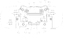
Fig. 1 is the front view of a kind of automatic transfer switching electric appliance preferred embodiment of the utility model;
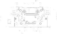
Fig. 2 is the vertical view of a kind of automatic transfer switching electric appliance preferred embodiment of the utility model;
Fig. 3 is the user mode figure when power supply square shaft commonly used is rotated counterclockwise an angle in a kind of automatic transfer switching electric appliance preferred embodiment of the utility model;
Fig. 4 is the user mode figure when the stand-by power supply square shaft turns clockwise an angle in a kind of automatic transfer switching electric appliance preferred embodiment of the utility model.
Embodiment
As shown in Figure 1, simultaneously referring to Fig. 2.In the preferred embodiment of the utility model, this automatic transfer switching electric appliance is mainly used in realizes that electric power system is from using the overlapping conversion that power supply switches to N level the stand-by power supply process always.It comprises the second moving contact draw-gear that is used to draw the first moving contact draw-gear of power supply N level moving contact 100 commonly used and power supply N level fixed contact commonly used 101 disconnections and is used to draw stand-by power supply N level moving contact 200 and 201 disconnections of stand-by power supply N level fixed contact.Wherein, The first moving contact draw-gear is fixedly connected with stand-by power supply square shaft 202; And be rotationally connected with power supply square shaft 102 commonly used through a N level connecting rod 301; The second moving contact draw-gear is fixedly connected with power supply square shaft 102 commonly used, and is rotationally connected with stand-by power supply square shaft 202 through the 2nd N level connecting rod 401.
The utility model mainly is applicable to power supply commonly used and the stand-by power supply with four levels, and power supply therefore commonly used and stand-by power supply all have the neutral line of a ground connection, and this neutral line is the N level of the utility model just.From power source conversion commonly used to the process of stand-by power supply, voltage can produce drift, the zero line phenomenon of soaring just, thereby influence lower end equipment, the reduction electric property.For fear of the soar appearance of phenomenon of zero line, the utility model utilization one in front and one in back is symmetricly set on the first moving contact draw-gear and the second moving contact draw-gear between power supply square shaft 102 commonly used and the stand-by power supply square shaft 202, and to guarantee in transfer process, to have at least a N level be closed:
The first moving contact draw-gear is fixedly connected with stand-by power supply square shaft 202; Therefore; When stand-by power supply square shaft 202 rotated counterclockwise, the N level moving contact 100 that can drive first moving contact draw-gear traction power supply commonly used separated with power supply N level fixed contact 101 commonly used, at this moment; Because the first moving contact draw-gear has an end to be rotationally connected with using power supply square shaft 102 always, power supply square shaft 102 therefore commonly used can not rotate.
When power supply square shaft 102 commonly used clockwise rotates; Because the second moving contact draw-gear is fixedly connected with using power supply square shaft 102 always, therefore, can drives second moving contact draw-gear traction stand-by power supply N level moving contact 200 and separate with stand-by power supply N level fixed contact 201; At this moment; Because the second moving contact draw-gear has one section to be rotationally connected with stand-by power supply square shaft 202, therefore, stand-by power supply square shaft 202 can not rotate.
More than be the first moving contact draw-gear and second moving contact draw-gear course of action separately; In the actual converted process; There are the state (state shown in Figure 1) of two fens position in power supply commonly used and stand-by power supply; Power supply promptly commonly used and stand-by power supply all are in the state of disconnection, so, and when power supply N level moving contact 100 commonly used and power supply N level fixed contact 101 after separatings commonly used; The stand-by power supply square shaft need clockwise rotate an angle 202 this moments; Let after power supply N level moving contact 100 commonly used and stand-by power supply N level fixed contact 101 closures, power supply square shaft 102 commonly used just can clockwise rotate, thereby lets stand-by power supply N level moving contact 200 separate with stand-by power supply N level fixed contact 201.
As shown in Figure 3; Further; The first moving contact draw-gear comprises that the first square shaft rocking bar, 300, the first square shaft rocking bars, 300 1 ends are fixedly connected with stand-by power supply square shaft 202, and an end of the other end and a N level connecting rod 301 is hinged; And N level connecting rod 301 1 ends and the first square shaft rocking bar 300 are hinged, and the other end can be connected with power supply square shaft 102 commonly used around power supply square shaft 102 commonly used with rotating freely.
The mode that the first square shaft rocking bar 300 is fixedly connected with stand-by power supply square shaft 202 can have multiple; In the preferred embodiment of the utility model; The first square shaft rocking bar, 300 1 ends are provided with the square opening with stand-by power supply square shaft 202 form fit, and the first square shaft rocking bar 300 is fixed on the stand-by power supply square shaft 202 through this square opening.In like manner; The one N level connecting rod 301 also can have multiple with the mode that power supply square shaft 102 commonly used is rotationally connected; In the preferred embodiment of the utility model, the other end of a N level connecting rod 301 can be connected with power supply square shaft 102 commonly used around power supply square shaft 102 commonly used through first axle sleeve 303 with rotating freely; And first axle sleeve, 303 1 ends and power supply square shaft 102 commonly used are rotationally connected, and hinged with an end of a N level connecting rod 301.
In order to draw power supply N level moving contact 100 commonly used; The other end of above-mentioned first axle sleeve 303 is hinged through first connecting rod 302 and power supply N level moving contact 100 commonly used; And in order to reset conveniently, first axle sleeve 303 also is provided with the torsion spring (not shown) with first connecting rod 302 hinged positions.
As shown in Figure 4, the second moving contact draw-gear comprises the second square shaft rocking bar 400.The second square shaft rocking bar, 400 1 ends are fixedly connected with power supply square shaft 102 commonly used; One end of the other end and the 2nd N level connecting rod 401 is hinged; And the 2nd N level connecting rod 401 1 ends and the second square shaft rocking bar 400 are hinged, and the other end can be connected with stand-by power supply square shaft 202 around stand-by power supply square shaft 202 with rotating freely.
The second square shaft rocking bar 400 can have multiple with the mode that power supply square shaft 102 commonly used is fixedly connected; In the preferred embodiment of the utility model; The second square shaft rocking bar, 400 1 ends are provided with and are used for the square opening that is connected with power supply square shaft 102 commonly used, and the second square shaft rocking bar 400 is fixed on the power supply square shaft 102 commonly used through this square opening.In like manner; The 2nd N level connecting rod 401 also can have multiple with the mode that stand-by power supply square shaft 202 is rotationally connected; In the preferred embodiment of the utility model, the other end of the 2nd N level connecting rod 401 can be connected with stand-by power supply square shaft 202 around stand-by power supply square shaft 202 through second axle sleeve 403 with rotating freely; And second axle sleeve, 403 1 ends and stand-by power supply square shaft 202 are rotationally connected, and hinged with an end of the 2nd N level connecting rod 401.
In order to draw stand-by power supply N level moving contact 200; The other end of above-mentioned second axle sleeve 403 is hinged through second connecting rod 402 and stand-by power supply N level moving contact 200, and second connecting rod 402 also is provided with the torsion spring (not shown) with stand-by power supply N level moving contact 200 hinged positions.
The automatic transfer switching electric appliance of the utility model can guarantee that the N level is not broken off in transfer process, soars thereby eliminate zero line, need not to raise the cost, and does not influence conversion speed, can obtain higher electric property.
Above embodiment only is the technical conceive and the characteristics of explanation the utility model, and its purpose is to let the personage who is familiar with this technology can understand content of the utility model and enforcement in view of the above, can not limit the protection range of the utility model.All equalizations of being done with the utility model claim scope change and modify, and all should belong to the covering scope of the utility model claim.
Claims (9)
1. automatic transfer switching electric appliance; Be used for realizing that electric power system switches to the overlapping conversion of stand-by power supply process N level from power supply commonly used; It is characterized in that, comprise the second moving contact draw-gear that is used to draw the first moving contact draw-gear of said power supply N level moving contact commonly used (100) and power supply N level fixed contact commonly used (101) disconnection and is used to draw said stand-by power supply N level moving contact (200) and stand-by power supply N level fixed contact (201) disconnection;
The said first moving contact draw-gear is fixedly connected with said stand-by power supply square shaft (202); And be rotationally connected through a N level connecting rod (301) and said power supply square shaft commonly used (102); The said second moving contact draw-gear is fixedly connected with said power supply square shaft commonly used (102), and is rotationally connected through the 2nd N level connecting rod (401) and said stand-by power supply square shaft (202).
2. automatic transfer switching electric appliance according to claim 1 is characterized in that, the said first moving contact draw-gear comprises the first square shaft rocking bar (300); The said first square shaft rocking bar (300) one ends are fixedly connected with said stand-by power supply square shaft (202); One end of the other end and a said N level connecting rod (301) is hinged; A said N level connecting rod (301) one ends and the said first square shaft rocking bar (300) are hinged, and the other end can be connected with said power supply square shaft commonly used (102) around said power supply square shaft commonly used (102) with rotating freely.
3. automatic transfer switching electric appliance according to claim 2; It is characterized in that; The said first square shaft rocking bar (300) one ends are provided with and are used for the square opening that cooperates with said stand-by power supply square shaft (202), and the said first square shaft rocking bar (300) is fixed on the said stand-by power supply square shaft (202) through said square opening.
4. automatic transfer switching electric appliance according to claim 2 is characterized in that, the other end of a said N level connecting rod (301) can be connected with said power supply square shaft commonly used (102) around said power supply square shaft commonly used (102) through first axle sleeve (303) with rotating freely;
Said first axle sleeve (303) one ends and said power supply square shaft commonly used (102) are rotationally connected, and hinged with an end of a said N level connecting rod (301).
5. automatic transfer switching electric appliance according to claim 4; It is characterized in that; The other end of said first axle sleeve (303) is hinged through first connecting rod (302) and said power supply N level moving contact commonly used (100), and said first axle sleeve (303) also is provided with torsion spring with the hinged position of said first connecting rod (302).
6. according to claim 1 or 2 each described automatic transfer switching electric appliances, it is characterized in that the said second moving contact draw-gear comprises the second square shaft rocking bar (400); The said second square shaft rocking bar (400) one ends are fixedly connected with said power supply square shaft commonly used (102); One end of the other end and said the 2nd N level connecting rod (401) is hinged; Said the 2nd N level connecting rod (401) one ends and the said second square shaft rocking bar (400) are hinged, and the other end can be connected with said stand-by power supply square shaft (202) around said stand-by power supply square shaft (202) with rotating freely.
7. automatic transfer switching electric appliance according to claim 6; It is characterized in that; The said second square shaft rocking bar (400) one ends are provided with and are used for the square opening that is connected with said power supply square shaft commonly used (102), and the said second square shaft rocking bar (400) is fixed on the said power supply square shaft commonly used (102) through said square opening.
8. automatic transfer switching electric appliance according to claim 6 is characterized in that, the other end of said the 2nd N level connecting rod (401) can be connected with said stand-by power supply square shaft (202) around said stand-by power supply square shaft (202) through second axle sleeve (403) with rotating freely;
Said second axle sleeve (403) one ends and said stand-by power supply square shaft (202) are rotationally connected, and hinged with an end of said the 2nd N level connecting rod (401).
9. automatic transfer switching electric appliance according to claim 8; It is characterized in that; The other end of said second axle sleeve (403) is hinged through second connecting rod (402) and said stand-by power supply N level moving contact (200), and said second connecting rod (402) also is provided with torsion spring with the hinged position of said stand-by power supply N level moving contact (200).
Priority Applications (1)
| Application Number | Priority Date | Filing Date | Title |
|---|---|---|---|
| CN2012200013012U CN202405134U (en) | 2012-01-04 | 2012-01-04 | Automatic change-over switch appliance |
Applications Claiming Priority (1)
| Application Number | Priority Date | Filing Date | Title |
|---|---|---|---|
| CN2012200013012U CN202405134U (en) | 2012-01-04 | 2012-01-04 | Automatic change-over switch appliance |
Publications (1)
| Publication Number | Publication Date |
|---|---|
| CN202405134U true CN202405134U (en) | 2012-08-29 |
Family
ID=46702766
Family Applications (1)
| Application Number | Title | Priority Date | Filing Date |
|---|---|---|---|
| CN2012200013012U Expired - Lifetime CN202405134U (en) | 2012-01-04 | 2012-01-04 | Automatic change-over switch appliance |
Country Status (1)
| Country | Link |
|---|---|
| CN (1) | CN202405134U (en) |
Cited By (2)
| Publication number | Priority date | Publication date | Assignee | Title |
|---|---|---|---|---|
| CN108206103A (en) * | 2017-12-29 | 2018-06-26 | 施耐德万高(天津)电气设备有限公司 | Neutral pole disjunction unit and the change-over switch for including the neutral pole disjunction unit |
| CN108648937A (en) * | 2018-05-29 | 2018-10-12 | 德布森电气(上海)有限公司 | A kind of dual power supply overlapping switch-on operating mechanism |
-
2012
- 2012-01-04 CN CN2012200013012U patent/CN202405134U/en not_active Expired - Lifetime
Cited By (3)
| Publication number | Priority date | Publication date | Assignee | Title |
|---|---|---|---|---|
| CN108206103A (en) * | 2017-12-29 | 2018-06-26 | 施耐德万高(天津)电气设备有限公司 | Neutral pole disjunction unit and the change-over switch for including the neutral pole disjunction unit |
| CN108648937A (en) * | 2018-05-29 | 2018-10-12 | 德布森电气(上海)有限公司 | A kind of dual power supply overlapping switch-on operating mechanism |
| CN108648937B (en) * | 2018-05-29 | 2023-09-19 | 德布森电气(上海)有限公司 | Dual-power overlapping closing operation mechanism |
Similar Documents
| Publication | Publication Date | Title |
|---|---|---|
| CN105225861A (en) | PC level double power supply automatic transfer switch | |
| CN202405134U (en) | Automatic change-over switch appliance | |
| CN203983204U (en) | A kind of residual current circuit breaker with reverse wiring structure | |
| CN204991513U (en) | PC level dual power automatic transfer switch | |
| CN202918048U (en) | Automatic transfer switching equipment | |
| CN204348602U (en) | A kind of novel breaker drive mechanism | |
| CN204537945U (en) | A kind of two circuit magnetic latching relay | |
| CN204390924U (en) | The dynamic contact mechanism of dual-power transfer switch | |
| CN204303669U (en) | A kind of phase-control permanent magnet vacuum circuit breaker | |
| CN202260003U (en) | Safe and energy-saving power strip | |
| CN206098319U (en) | But remote control's earth -leakage protector | |
| CN203118869U (en) | Relay control circuit | |
| CN202454485U (en) | Rigid power transmission device | |
| CN204155886U (en) | Circuit breaker rotary type double-breakpoint structure of contact terminal | |
| CN204118857U (en) | A kind of divide-shut brake automatic control equipment and system | |
| CN203398425U (en) | Safe dustproof plug board | |
| CN204332873U (en) | Circuit breaker reclosing device Handleset | |
| CN202905548U (en) | Novel rotary switch | |
| CN203117213U (en) | A centrifugal bidirectional speed relay | |
| CN201328094Y (en) | Motor control circuit | |
| CN203351880U (en) | Intelligent energy-saving socket | |
| CN204289304U (en) | A kind of moving contact component of circuit breaker | |
| CN204577332U (en) | A kind of energy storage motor controlling organization | |
| CN201332177Y (en) | Induction type linkage mains socket board | |
| CN201504090U (en) | Zero line open circuit protection device for low-voltage distribution network |
Legal Events
| Date | Code | Title | Description |
|---|---|---|---|
| C14 | Grant of patent or utility model | ||
| GR01 | Patent grant | ||
| CX01 | Expiry of patent term |
Granted publication date: 20120829 |
|
| CX01 | Expiry of patent term |