The model utility content
The purpose of the utility model is exactly in order to address the above problem, and a kind of novel gas decompressor is provided.
To achieve these goals, the utility model adopts following technological scheme:
A kind of novel gas decompressor comprises lower cover, loam cake and valve body, and said valve inner is provided with dividing plate and is positioned at the one-level of dividing plate upper and lower sides, secondary valve pocket; This dividing plate is provided with the valve pocket through hole, is positioned at the valve pocket through hole and is provided with pressure stabilizing cavity valve core case screw hole all around, and lower cover passes through the valve body bolt in one-level valve pocket below; Be equiped with one group of reduction valve parts in lower cover and the one-level valve pocket, said one-level, secondary valve pocket sidewall are respectively equipped with air inlet seat and air outlet adapter, are provided with decompressor main valve plug assembly between air inlet seat and one-level valve pocket; Loam cake in secondary valve pocket top, is provided with pressure stabilizing cavity diaphragm and sealing cover through the valve body bolt between loam cake and valve body, this pressure stabilizing cavity diaphragm bilateral symmetry is provided with upper and lower voltage stabilizing sheet; Last voltage stabilizing sheet is provided with pressure stabilizing cavity spring and pressure adjusting spring pole socket; It is outside that the pressure stabilizing cavity spring is located at the pressure adjusting spring pole socket, establishes the pressure adjusting spring bar in the said pressure adjusting spring pole socket, it is characterized in that; Pressure stabilizing cavity valve core case screw hole place around the said valve pocket through hole is fixed with the flat valve core print seat; Said flat valve core print seat is equiped with the flat valve core, wherein
Said flat valve core print seat has the cylindrical sleeve of a band shape bottom and wherein limits a voltage stabilizing passage;
Said flat valve core has the poppet shaft that the tip, of being located at the valve pocket through hole is arranged in voltage stabilizing passage, sealing cover, following voltage stabilizing sheet, pressure stabilizing cavity diaphragm successively, goes up the voltage stabilizing sheet; Said poppet shaft is provided with and is positioned at the first terminal thread section of tip, second thread section terminal with being located at poppet shaft, and the end of said flat valve core is fixed in the inner chamber of pressure adjusting spring seat through the pressure stabilizing cavity nut;
Be equiped with the taper joint that is connected with flat valve core first thread section in the said cylindrical sleeve; Establish first, second step-like groove in this taper joint; Second step shape groove inward flange is provided with the cylindrical interior volume that connects towards taper joint cephalad direction, and this inner chamber is provided with the internal thread with the outside thread coupling of first thread section.
Preferably, said first step shape groove is equiped with spool O type circle.
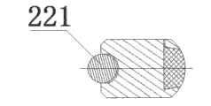
Preferably, said decompressor main valve plug assembly is provided with circular groove towards one-level valve pocket one side, and this circular groove is inlaid with steel ball.
The beneficial effect of the utility model is: (1) is by the flat valve core print seat and be fixed in the flat valve cored structure that the flat valve core on the flat valve core print seat constitutes, and guarantees the gas pressure reducers smooth running; (2) decompressor main valve plug assembly is inlayed steel ball, makes prolong greatly its working life.
Embodiment
For technological means, creation characteristic that the utility model is realized, reach purpose and be easy to understand understanding with effect, below in conjunction with concrete diagram, further set forth the utility model.
A kind of novel gas decompressor comprises lower cover, loam cake and valve body, and said valve inner is provided with dividing plate and is positioned at the one-level of dividing plate upper and lower sides, secondary valve pocket; This dividing plate is provided with the valve pocket through hole, is positioned at the valve pocket through hole and is provided with pressure stabilizing cavity valve core case screw hole all around, and this pressure stabilizing cavity valve core case screw hole is used to install the flat valve core print seat; Lower cover in one-level valve pocket below, is equiped with one group of reduction valve parts through the valve body bolt in lower cover and the one-level valve pocket, said one-level, secondary valve pocket sidewall are respectively equipped with air inlet seat and air outlet adapter; Be provided with decompressor main valve plug assembly between air inlet seat and one-level valve pocket; Loam cake in secondary valve pocket top, is provided with pressure stabilizing cavity diaphragm and sealing cover through the valve body bolt between loam cake and valve body, this pressure stabilizing cavity diaphragm bilateral symmetry is provided with upper and lower voltage stabilizing sheet; Last voltage stabilizing sheet is provided with pressure stabilizing cavity spring and pressure adjusting spring pole socket; It is outside that the pressure stabilizing cavity spring is located at the pressure adjusting spring pole socket, establishes the pressure adjusting spring bar in the said pressure adjusting spring pole socket, and the pressure stabilizing cavity valve core case screw hole place around the said valve pocket through hole is fixed with the flat valve core print seat; Said flat valve core print seat is equiped with the flat valve core; Wherein, shown in Fig. 5 a, 5b, said flat valve core print seat 36 has the cylindrical sleeve of a band shape bottom 361 and wherein limits a voltage stabilizing passage 362; Said flat valve core has the poppet shaft that the tip, of being located at the valve pocket through hole is arranged in voltage stabilizing passage, sealing cover, following voltage stabilizing sheet, pressure stabilizing cavity diaphragm successively, goes up the voltage stabilizing sheet; Said poppet shaft is provided with and is positioned at terminal first thread section 394, second thread section 393 terminal with being located at poppet shaft in tip, and the end of said flat valve core is fixed in the inner chamber of pressure adjusting spring seat through the pressure stabilizing cavity nut;
Referring to Fig. 4 a, 4b; Be equiped with the taper joint 390 that is connected with flat valve core first thread section in the said cylindrical sleeve; Establish first, second step-like groove 391,392 in this taper joint; Second step shape groove inward flange is provided with the cylindrical interior volume that connects towards taper joint cephalad direction, and this inner chamber is provided with the internal thread with the outside thread coupling of first thread section, and said first step shape groove is equiped with spool O type circle 56.
Shown in Fig. 6 a, 6b, said decompressor main valve plug assembly 22 is provided with circular groove towards one-level valve pocket one side, and this circular groove is inlaid with steel ball 221.
Describe in detail below in conjunction with accompanying drawing:
Shown in Fig. 1~3; The novel gas decompressor comprises: loam cake 53, lower cover 3 and be located at the valve body 25 between the upper and lower cover, and loam cake 53, lower cover 3 are fixed in the upper and lower end of valve body through eight valve body bolts 1; This valve body bolt sleeve is provided with elastic washer 2, and the loam cake sidewall is provided with vacuum tube joint 54;
Said cover cavity down is provided with fixedly sebific duct 5 of spring, and it is arranged with relief chamber spring 4, between valve body and lower cover, is provided with relief chamber diaphragm 9; This relief chamber diaphragm middle part is provided with through hole and annular is provided with four bolts hole; Said relief chamber diaphragm 9 nearly lower cover ends are provided with decompression sheet 8, and rocker arm assembly 11 is provided with male end and is arranged in the through hole of relief chamber diaphragm and stretches into down cover cavity, is fixed through relief chamber nut 6; Relief chamber nut 6 is arranged with relief chamber bullet pad 7; Said relief chamber diaphragm 9 lower cover one sides far away are provided with decompression holder diaphragm 10, and it is sheathed on the rocker arm assembly 11, and the rocker arm assembly place also is provided with relief chamber pan bolt 12;
Said rocker arm assembly 11 is provided with rocking arm head of the horse fixing pin 13;
Said valve body suction port ecto-entad is installed air inlet seat 20, decompressor main valve plug assembly 22 in relief chamber external admission seat 15, straight two pass joints 17, the relief chamber successively; Wherein the outside thread of relief chamber external admission seat 15 settings is connected with the internal thread coupling of air inlet seat 20 heads setting in the relief chamber; Straight two pass joints 17 are sheathed on the relief chamber external admission seat 15; And air inlet seat 20 contacting points are provided with two logical O type circles 16 in straight two pass joints, 17 two end part and relief chamber external admission seat 15, relief chamber; Relief chamber external admission seat 15 through hole ends are provided with pad 18, high-pressure filteration sheet 19 near the 20 inner chamber places of air inlet seat in the relief chamber; Air inlet seat 20 is arranged with air inlet seat aluminium pad 21 in the high pressure in the said relief chamber, and said valve body suction port place downside is installed two water swivels 14, and this water swivel links to each other with valve body suction port sidewall through engage thread; Valve body suction port top is equiped with water cycle bolt 24, and this water cycle bolt is provided with cooling-water temperature sensor;
Establish one-level valve pocket 23 and secondary valve pocket 34 in the said valve body; The sidewall that said valve body is positioned at secondary valve pocket 34 positions is provided with is with externally threaded air outlet adapter 26; This air outlet adapter is connected with spray rail suction port through the gas pressure solenoid, is positioned on one-level valve pocket 23 sidewalls also to be provided with relief valve port, and this relief valve port is equiped with emergency valve seat 31; Its front end is provided with outside thread; The afterbody inner chamber is provided with inner bolt, and the thread head of this emergency valve seat is provided with safety valve O type circle 30, the emergency valve seat bolt 32 of establishing safety valve glue head 27, safety valve inner core 28, safety valve spring 29 in the emergency valve seat 31 and being connected with the emergency valve seat afterbody through screw thread;
Secondary valve pocket 34 sidewalls of valve body are provided with perforate, and this perforate is provided with internal thread, are connected with externally threaded pressure stabilizing cavity plug screw 33 through this internal thread coupling, are provided with pressure stabilizing cavity bolt O type circle 57 at this pressure stabilizing cavity plug screw thread head afterbody;
The bottom of secondary valve pocket 34 is fixed with flat valve core print seat 36 through flat valve core print seat screw 37; Be provided with valve seat O type circle 35 between this flat valve core print seat and secondary valve pocket bottom; Flat valve core print seat 36 is equiped with flat valve core 39; 36 of flat valve core 39 and flat valve core print seats are provided with spool O core circle 38, and 42 of flat valve core and sealing covers also are provided with flat valve core O type circle 56;
Be provided with pressure stabilizing cavity diaphragm 46 between loam cake and valve body, these pressure stabilizing cavity diaphragm 46 middle parts are provided with through hole, are provided with four bolts hole all around, are provided with sealing cover 42 at pressure stabilizing cavity diaphragm 46 near secondary valve pocket 34 1 sides, are provided with sealing cover O type circle 40 between sealing lid and body wall; Sealing lid 42 is equiped with sealing cover vacuum connect 41; The sealing cover place is provided with sealing cover center O type circle 43; Pressure stabilizing cavity diaphragm 46 both sides are equipped with voltage stabilizing sheet 44a, following voltage stabilizing sheet 44b, and 46 on voltage stabilizing sheet and pressure stabilizing cavity diaphragm are provided with voltage stabilizing sheet O type circle 45, and last voltage stabilizing sheet 44b place is provided with pressure stabilizing cavity bullet pad 47; This pressure stabilizing cavity bullet pad 47 is provided with the pressure stabilizing cavity nut 48 that is connected with flat valve core 39 aft mounted outside threads; Pressure stabilizing cavity spring 49 1 ends are fixed on the voltage stabilizing sheet 44b, and pressure stabilizing cavity spring 49 is wrapped on the pressure adjusting spring pole socket 51, establish pressure adjusting spring bar 50 in the said pressure adjusting spring pole socket 51; This pressure adjusting spring bar is arranged with pressure adjusting spring bar O type circle 52, and loam cake 53 tops are provided with loam cake cover plate 55.
The above is merely the preferred implementation of the utility model, and the protection domain of the utility model is not limited in above-mentioned mode of execution, and every technological scheme that belongs to the utility model principle all belongs to the protection domain of the utility model.For a person skilled in the art, some improvement of under the prerequisite of the principle that does not break away from the utility model, carrying out, these improve the protection domain that also should be regarded as the utility model.