CN202344046U - Steel tube inner wall grooving machine - Google Patents
Steel tube inner wall grooving machine Download PDFInfo
- Publication number
- CN202344046U CN202344046U CN2011204993725U CN201120499372U CN202344046U CN 202344046 U CN202344046 U CN 202344046U CN 2011204993725 U CN2011204993725 U CN 2011204993725U CN 201120499372 U CN201120499372 U CN 201120499372U CN 202344046 U CN202344046 U CN 202344046U
- Authority
- CN
- China
- Prior art keywords
- sleeve
- axial
- steel pipe
- steel tube
- inner sleeve
- Prior art date
- Legal status (The legal status is an assumption and is not a legal conclusion. Google has not performed a legal analysis and makes no representation as to the accuracy of the status listed.)
- Expired - Fee Related
Links
Images


Landscapes
- Turning (AREA)
Abstract
The utility model relates to the steel tube processing field, particularly relates to a steel tube inner wall grooving machine. The steel tube inner wall grooving machine is realized by the following technical scheme: the steel tube inner wall grooving machine comprises a base, a steel tube control structure arranged on the base, and a blade carrier structure for grooving on the steel tube inner wall. The steel tube control structure comprises a sleeve support, an external sleeve which is rotationally connected with the sleeve support and passes through the two ends of the sleeve support, an internal sleeve which is sleeved with the external sleeve and extends out the two ends of the external sleeve, and a drive motor which is connected with one end of the external sleeve through a belt, wherein the end of the external sleeve is far away from the blade carrier structure; and one end of the internal sleeve, close to the blade carrier structure, is provided with a plurality of fixing claw pieces, and the wall of each fixing claw piece gradually thickens from the joint between the fixing claw piece and the internal sleeve to the axially-extending free end of the fixing claw piece. The steel tube inner wall grooving machine is simple in operation for fastening a steel tube, and is not easy to damage the sleeve.
Description
Technical field
the utility model relates to the steel pipe manufacture field, and particularly the steel pipe inwall plays scouring machine.
Background technology
steel pipe inwall of the prior art plays scouring machine when work, and the direct swelling of steel pipe is in the sleeve pipe by the drive motors driven rotary, however the mode complex operation of this fastening steel pipe and fragile sleeve pipe.
The utility model content
The purpose of
the utility model provides the steel pipe inwall and plays scouring machine, and its fastening steel pipe mode is simple to operate, and is difficult for damaging sleeve pipe.
The above-mentioned technical purpose of
the utility model is achieved through following technical scheme: the steel pipe inwall plays scouring machine; Comprise base, be located at the steel pipe control structure on the base and be used for cutter frame structure in the grooving of steel pipe inwall, said steel pipe control structure comprises sleeve bearing, be rotationally connected with sleeve bearing and run through the sleeve bearing two ends outer tube, with outer tube socket and the drive motors that passes the inner sleeve at outer tube two ends, be connected through belt away from an end of cutter frame structure with outer tube; Said outer sleeve inner wall is provided with the raised line of axial distribution, and the outer wall of inner sleeve is provided with the groove that matches with raised line; Said inner sleeve has the solid sheet of multi-disc pawl near an end of cutter frame structure; The medial surface of the solid sheet of said pawl is arcuation; And the radius of this medial surface is identical with the inner sleeve inside radius, and the wall thickness of the solid sheet of pawl extends axially the free end of consolidating sheet to pawl and is thickening shape gradually along the junction of the solid sheet of pawl and inner sleeve; Said inner sleeve is installed with spacing collar away from an end of cutter frame structure, be provided with between spacing collar and the outer tube to be placed in the outer draw ring of inner sleeve, and a side of draw ring is hinged with the support column that is fixed on the sleeve bearing.
said outer sleeve inner wall is provided with the raised line of axial distribution, and the outer wall of inner sleeve is provided with the groove that matches with raised line, makes outer tube and inner sleeve can realize axial displacement between the two, but can not produce relative rotation; After inserting inner sleeve to steel pipe, draw ring is torn to spacing collar, thereby made spacing collar drive inner sleeve and outer tube produce axial displacement, thereby and make the solid sheet of pawl owing to receive the inwardly gathering of pressure of outer sleeve inner wall, thus make fixedly steel pipe of the solid sheet of pawl; After machining, as long as with the inner sleeve pushed home, can unload steel pipe, simple to operate, and easy damaged sleeve pipe not.
are preferred as the utility model, also are installed with pull bar on the said draw ring.
Being provided with of
pull bar made things convenient for tearing of draw ring.
are preferred as the utility model, said cutter frame structure comprises the axial slide rail be located on the base, be slidingly connected to axial slide on the axial slide rail, be located at axial slide upper surface radially slide rail, be slidingly connected to radially slide rail and tool rest that be fixed with cutter.
realize that through above-mentioned the setting tool rest is axially moving with the footpath makes progress.
are preferred as the utility model, said cutter frame structure also comprise the axial rotating disk that is rotationally connected with on the base, two ends respectively with the hinged axial links of axial slide and axial rotating disk, be rotationally connected with radially rotating disk on the base, two ends respectively with tool rest and the hinged radial link of rotating disk radially.
through the rotation of corresponding rotating disk, is axially moving with the footpath makes progress to realize tool rest.
are preferred as the utility model, are fixedly connected with axial pull bar on the said axial rotating disk; Radially be fixedly connected with radially pull bar on the rotating disk.
The rotation of corresponding rotating disk is realized through axial pull bar of pulling or pull bar radially in
.
in sum, the utlity model has following beneficial effect: the utility model is simple in structure, and is easy to implement, and simple to operate, and also easy damaged sleeve pipe not, and working (machining) efficiency is high.
Description of drawings
Fig. 1 is the example structure sketch map;
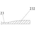
Fig. 2 is the solid sheet cutaway view of pawl;
Fig. 3 is the outer tube cutaway view;
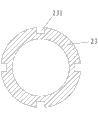
Fig. 4 is the inner sleeve cutaway view.
Among
figure, 1, base, 21, sleeve bearing, 211, support column, 22, outer tube, 221, raised line; 23, inner sleeve, 231, groove, 232, the solid sheet of pawl, 233, spacing collar, 234, draw ring, 235, pull bar; 24, drive motors, 31, axial slide rail, 32, axial slide, 33, slide rail radially, 34, tool rest, 341, cutter; 35, axial rotating disk, 351, axial pull bar, 36, axial links, 37, rotating disk radially, 371, pull bar radially, 38, radial link.
The specific embodiment
are done further explain below in conjunction with accompanying drawing to the utility model.
this specific embodiment only is the explanation to the utility model; It is not the restriction to the utility model; Those skilled in the art can make the modification that does not have creative contribution to present embodiment as required after reading this specification, but as long as in the claim scope of the utility model, all receive the protection of Patent Law.
embodiment: shown in Fig. 1 to 4, the steel pipe inwall plays scouring machine, comprises base 1, is located at the steel pipe control structure on the base 1 and is used for the cutter frame structure in the grooving of steel pipe inwall.
steel pipe control structure comprises sleeve bearing 21, be rotationally connected with sleeve bearing 21 and run through sleeve bearing 21 two ends outer tube 22, with outer tube 22 sockets and the drive motors 24 that passes the inner sleeve 23 at outer tube 22 two ends, be connected through belt away from an end of cutter frame structure with outer tube 22; Outer tube 22 inwalls are provided with the raised line 221 of axial distribution, and the outer wall of inner sleeve 23 is provided with the groove 231 that matches with raised line 221; Said inner sleeve 23 has the solid sheet 232 of multi-disc pawl near an end of cutter frame structure; The medial surface of the solid sheet 232 of pawl is arcuation; And the radius of this medial surface is identical with inner sleeve 23 inside radius, and the wall thickness of the solid sheet 232 of pawl extends axially along the junction of the solid sheet 232 of pawl and inner sleeve 23 to the free end of the solid sheet 232 of pawl and is thickening shape gradually; Said inner sleeve 23 is installed with spacing collar 233 away from an end of cutter frame structure, be provided with the draw ring 234 that is placed in outside the inner sleeve 23 between spacing collar 233 and the outer tube 22, and a side of draw ring 234 is hinged with the support column 211 that is fixed on the sleeve bearing 21; Also be installed with pull bar 235 on the draw ring 234.
cutter frame structure comprises the axial slide rail of being located on the base 1 31; Be slidingly connected to the axial slide 32 on the axial slide rail 31; Be located at the radially slide rail 33 of axial slide 32 upper surfaces; Be slidingly connected to radially slide rail 33 and tool rest 34 that be fixed with cutter 341; Be rotationally connected with the axial rotating disk 35 on the base 1; The axial links 36 that two ends are hinged with axial slide 32 and axial rotating disk 35 respectively; Be rotationally connected with the radially rotating disk 37 on the base 1; Two ends respectively with tool rest 34 and the hinged radial link 38 of rotating disk 37 radially; Axially be fixedly connected with axial pull bar 351 on the rotating disk 35; Radially be fixedly connected with radially pull bar 371 on the rotating disk 37.
Claims (5)
1. the steel pipe inwall plays scouring machine; Comprise base (1), be located at the steel pipe control structure on the base (1) and be used for cutter frame structure in the grooving of steel pipe inwall; It is characterized in that, said steel pipe control structure comprises sleeve bearing (21), be rotationally connected with sleeve bearing (21) and run through sleeve bearing (21) two ends outer tube (22), with outer tube (22) socket and the drive motors (24) that passes the inner sleeve (23) at outer tube (22) two ends, be connected through belt away from an end of cutter frame structure with outer tube (22); Said outer tube (22) inwall is provided with the raised line (221) of axial distribution, and the outer wall of inner sleeve (23) is provided with the groove (231) that matches with raised line (221); Said inner sleeve (23) has the solid sheet (232) of multi-disc pawl near an end of cutter frame structure; The medial surface of the solid sheet (232) of said pawl is arcuation; And the radius of this medial surface is identical with inner sleeve (23) inside radius, and the wall thickness of the solid sheet (232) of pawl extends axially along the junction of the solid sheet (232) of pawl and inner sleeve (23) to the free end of the solid sheet (232) of pawl and is thickening shape gradually; Said inner sleeve (23) is installed with spacing collar (233) away from an end of cutter frame structure; Be provided with between spacing collar (233) and the outer tube (22) and be placed in the outer draw ring (234) of inner sleeve (23), and a side of draw ring (234) is hinged with the support column (211) that is fixed on the sleeve bearing (21).
2. steel pipe inwall according to claim 1 plays scouring machine, it is characterized in that, also is installed with pull bar (235) on the said draw ring (234).
3. steel pipe inwall according to claim 1 plays scouring machine; It is characterized in that, said cutter frame structure comprises the axial slide rail (31) be located on the base (1), be slidingly connected to axial slide (32) on the axial slide rail (31), be located at axial slide (32) upper surface radially slide rail (33), be slidingly connected to radially slide rail (33) and tool rest that be fixed with cutter (341) (34).
4. steel pipe inwall according to claim 3 plays scouring machine; It is characterized in that, said cutter frame structure also comprise the axial rotating disk (35) that is rotationally connected with on the base (1), two ends respectively with the hinged axial links (36) of axial slide (32) and axial rotating disk (35), be rotationally connected with radially rotating disk (37) on the base (1), two ends respectively with tool rest (34) and the hinged radial link (38) of rotating disk (37) radially.
5. a kind of steel pipe inwall according to claim 4 plays scouring machine, it is characterized in that, is fixedly connected with axial pull bar (351) on the said axial rotating disk (35); Radially be fixedly connected with radially pull bar (371) on the rotating disk (37).
Priority Applications (1)
| Application Number | Priority Date | Filing Date | Title |
|---|---|---|---|
| CN2011204993725U CN202344046U (en) | 2011-12-05 | 2011-12-05 | Steel tube inner wall grooving machine |
Applications Claiming Priority (1)
| Application Number | Priority Date | Filing Date | Title |
|---|---|---|---|
| CN2011204993725U CN202344046U (en) | 2011-12-05 | 2011-12-05 | Steel tube inner wall grooving machine |
Publications (1)
| Publication Number | Publication Date |
|---|---|
| CN202344046U true CN202344046U (en) | 2012-07-25 |
Family
ID=46533075
Family Applications (1)
| Application Number | Title | Priority Date | Filing Date |
|---|---|---|---|
| CN2011204993725U Expired - Fee Related CN202344046U (en) | 2011-12-05 | 2011-12-05 | Steel tube inner wall grooving machine |
Country Status (1)
| Country | Link |
|---|---|
| CN (1) | CN202344046U (en) |
Cited By (2)
| Publication number | Priority date | Publication date | Assignee | Title |
|---|---|---|---|---|
| CN102398084A (en) * | 2011-12-05 | 2012-04-04 | 浙江华顺椅业有限公司 | Steel pipe inner wall grooving machine |
| CN104209597A (en) * | 2014-09-04 | 2014-12-17 | 上海振华重工(集团)股份有限公司 | Notch chamfering machine of steel pipe |
-
2011
- 2011-12-05 CN CN2011204993725U patent/CN202344046U/en not_active Expired - Fee Related
Cited By (3)
| Publication number | Priority date | Publication date | Assignee | Title |
|---|---|---|---|---|
| CN102398084A (en) * | 2011-12-05 | 2012-04-04 | 浙江华顺椅业有限公司 | Steel pipe inner wall grooving machine |
| CN104209597A (en) * | 2014-09-04 | 2014-12-17 | 上海振华重工(集团)股份有限公司 | Notch chamfering machine of steel pipe |
| CN104209597B (en) * | 2014-09-04 | 2016-07-06 | 上海振华重工(集团)股份有限公司 | Steel pipe otch beveler |
Similar Documents
| Publication | Publication Date | Title |
|---|---|---|
| CN202344046U (en) | Steel tube inner wall grooving machine | |
| CN203901037U (en) | Machine for removing burrs from hole in OCV | |
| CN202623361U (en) | Creasing machine for carton | |
| CN202344018U (en) | Cutting machine | |
| CN105692317A (en) | Dyeing and rolling equipment | |
| CN203124825U (en) | Cut-off machine for thin-walled tubes | |
| CN205128976U (en) | Rotatory compact form drilling combination vertical numerically -controlled machine tool that expands | |
| CN203110394U (en) | Carton printing and grooving all-in-one machine | |
| CN102398084A (en) | Steel pipe inner wall grooving machine | |
| CN102744467A (en) | Coaxial master-slave series chamfer cutter | |
| CN204160524U (en) | Large caliber rubber tube cutting machine | |
| CN202344267U (en) | Fastening structure applicable to steel pipe inner wall grooving machine | |
| CN202556476U (en) | Cutter device of paper cutting machine | |
| CN104625237A (en) | Manual two-way chamfering tool | |
| CN203266745U (en) | Pipe cutting machine overturning device | |
| CN210210643U (en) | Quick tool setting mechanism of splitting machine | |
| CN202726181U (en) | Pipe cutter knife for pipe cutter | |
| CN102423857A (en) | Fastening structure suitable for steel pipe inner wall grooving machine | |
| CN102489737A (en) | Punching device and punching machine using same | |
| CN207372438U (en) | A kind of milling side slotting all-in-one machine side necking tool | |
| CN102677722B (en) | Split bucket of chain type grooving machine | |
| CN203936590U (en) | A kind of protecgulum and rear bearing press | |
| CN204525581U (en) | One way of life paper cutter device | |
| CN205128975U (en) | Fixed position rotation is bloated, and vertical numerically -controlled machine tool is made up in compact form drilling | |
| CN202684184U (en) | Rotating tool rest used in pipe cutter |
Legal Events
| Date | Code | Title | Description |
|---|---|---|---|
| C14 | Grant of patent or utility model | ||
| GR01 | Patent grant | ||
| C17 | Cessation of patent right | ||
| CF01 | Termination of patent right due to non-payment of annual fee |
Granted publication date: 20120725 Termination date: 20131205 |