CN202326240U - Closed type compressor and refrigeration circulating device - Google Patents
Closed type compressor and refrigeration circulating device Download PDFInfo
- Publication number
- CN202326240U CN202326240U CN2011204494089U CN201120449408U CN202326240U CN 202326240 U CN202326240 U CN 202326240U CN 2011204494089 U CN2011204494089 U CN 2011204494089U CN 201120449408 U CN201120449408 U CN 201120449408U CN 202326240 U CN202326240 U CN 202326240U
- Authority
- CN
- China
- Prior art keywords
- bearing
- running shaft
- main bearing
- type compressor
- roller
- Prior art date
- Legal status (The legal status is an assumption and is not a legal conclusion. Google has not performed a legal analysis and makes no representation as to the accuracy of the status listed.)
- Expired - Lifetime
Links
Images



Landscapes
- Applications Or Details Of Rotary Compressors (AREA)
Abstract
The utility model relates to a closed type compressor. A compressing mechanism part comprises a main bearing, a supplementary bearing and two air cylinders arranged between the main bearing and the supplementary bearing, wherein the main bearing is arranged at a position close to an electromotor part and is used for supporting a rotating shaft, the supplementary bearing is arranged at a position far from the electromotor part and is used for supporting the rotating shaft, an upper bearing member is arranged between the upper part of a closed container and the electromotor part, and the upper bearing member is provided with a rolling bearing clamped with the rotating shaft and a bearing bracket for keeping the rolling bearing. The closed type compressor is characterized in that when the outside diameter of a freely rotating roller contained in each air cylinder is Dr, the height of the roller is Hr, the inside diameter of the main bearing is Dm and the total length of the main bearing is Lm, the following expression (Dr*Hr)/(Dm*Lm)=1-1.5 can be met.
Description
Technical field
Freeze cycle (cycle) device that the mode of execution of the utility model relates to a kind of hermetic type compressor and is incorporated with this hermetic type compressor, said hermetic type compressor is improved the structure of the bearing of supporting rotating shaft, raising that can implementation efficiency.
Background technique
Used hermetic type compressor contains motor part and is linked to the compression mechanical part of this motor part via running shaft in the freezing cycle device of refrigerating machine or air-conditioning etc. in seal container.And running shaft is supported with the supplementary bearing that is located at the bottom by the main bearing on the top that is located at compression mechanical part.
And, through above-mentioned compressor structure portion compression and the coolant gas of high-pressure trend temporarily is ejected in the seal container from ejiction opening, and then be led to gas passageway set in the motor part, and be ejected to external mechanical from the spraying pipe that is connected in seal container.At this moment, under the action of pressure of the coolant gas of high-pressure trend through compressing, compressive load is in running shaft.Therefore can produce following phenomenon, that is: be accompanied by the centrifugal force that the rotation of running shaft brings, running shaft occurs bending and deformation and tilts with respect to the central shaft of said main bearing, presses thereby main bearing is produced big face.
Therefore, in order to suppress the bending of running shaft, near the upper bearing member (the 3rd bearing) (for example, with reference to patent documentation 1) the upper end that proposes to have a kind of hermetic type compressor, its top to be provided with supporting rotating shaft in motor part.According to this kind hermetic type compressor, can reduce the bending of running shaft, thereby being pressed, the face that acts on main bearing reduces.
[existing technology document]
[patent documentation]
[patent documentation 1] Japanese Patent Laid is opened the 2004-3406 communique
But in aforesaid hermetic type compressor, the bending of considering to reduce running shaft to be to keep reliability, the design load that again can implementation efficiency improves.
The model utility content
The utility model is in view of this to plant problem and create; Its purpose is the freezing cycle device that a kind of hermetic type compressor is provided and uses this hermetic type compressor; Said hermetic type compressor can reduce the bending of running shaft to keep reliability; And can reduce the loss and the raising of implementation efficiency, and can realize miniaturization.
The hermetic type compressor of the mode of execution of the utility model is that motor part is accommodated on the top in seal container; And accommodate via running shaft in the bottom of said seal container and to come compressor driven structure portion by said motor part, said compression mechanical part comprises main bearing, supplementary bearing and two cylinders, and said main bearing is located near the position of said motor part and supports said running shaft; Said supplementary bearing is located at away from the position of said motor part and supports said running shaft; Said two cylinders are located between said main bearing and the supplementary bearing, between the top and said motor part of said seal container, are provided with the upper bearing member; This upper bearing member has rolling bearing that engages with said running shaft and the bearing bracket stand that keeps this rolling bearing; This hermetic type compressor is characterised in that, the outside dimension of the rotation roller freely of accommodating when the inside of establishing said cylinder is Dr, and the height dimension of roller is Hr; The internal diameter size of main bearing is Dm; When the total length of main bearing is of a size of Lm, the formula below satisfying
(Dr×Hr)/(Dm×Lm)=1~1.5。
The freezing cycle device of the mode of execution of the utility model comprises according to above-mentioned hermetic type compressor, condenser, expansion gear and vaporizer.
(effect of model utility)
Mode of execution according to the utility model; The freezing cycle device that a kind of hermetic type compressor can be provided and use this hermetic type compressor; Said hermetic type compressor can be kept reliability, and can reduce the loss and the raising of implementation efficiency, and can realize miniaturization.
Description of drawings
Fig. 1 is hermetic type compressor and the structural drawing that uses the freezing cycle device of this hermetic type compressor of the mode of execution of expression the utility model.
Fig. 2 is the explanatory drawing that schematically shows the deformation state of the running shaft of compressive load when running shaft.
Fig. 3 (a), Fig. 3 (b) are the action specification figure that compression mechanical part is represented on the plane.
Fig. 4 (a), Fig. 4 (b) are that likewise the action specification figure of compression mechanical part is represented on the plane.
Fig. 5 (a), Fig. 5 (b) are that likewise the action specification figure of compression mechanical part is represented on the plane.
Fig. 6 is shown schematically in the structure that is provided with the upper bearing member, the explanatory drawing of the deformation state of the running shaft of compressive load when running shaft.
Fig. 7 is the expression set quota (chart of the relation that Dr * Hr/Dm * Lm) and the centre plane of main bearing are pressed.
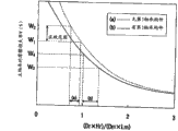
Fig. 8 is the expression set quota (chart of Dr * Hr/Dm * Lm) and the relation of the frictional loss rate of main bearing.
Fig. 9 is the expression set quota (chart of V * L3/I) and the relation of the bend angle of running shaft.
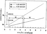
Figure 10 is the expression set quota (chart of V * L3/I) and the relation of the frictional loss rate of bearing.
[explanation of symbol]
1: freezing cycle device
2: condenser
3: expansion gear
4: vaporizer
5: liquid-storage container
6: running shaft
7: the upper bearing member
8: blade
8A: blade groove
10: hermetic type compressor
11: seal container
12: spraying pipe
13: power supply terminal
20: motor part
21: concentrated winding stator
22: rotor
30: compression mechanical part
30A: the 1st compression mechanical part
30B: the 2nd compression mechanical part
31A: the 1st cylinder
31B: the 2nd cylinder
32: the intermediate section dividing plate
33A: main bearing
33B: supplementary bearing
34,35: valve gap
35a: inner cap
36: bolt
37A, 37B: eccentric part
38A, 38B: roller
39A: the 1st cylinder chamber
39B: the 2nd cylinder chamber
71: the axis of rolling
72: bearing bracket stand
D1: the external diameter of rotor 22
D2: the internal diameter of rotor 22
Dm: the internal diameter size of main bearing
Dr: the outside dimension of roller
DS: the external diameter of running shaft 6
H: high pressure side
Hr: the height dimension of roller
L: low voltage side
Lm: the total length size of main bearing 33A
In: pump port
Out: otch is used in ejection
Embodiment
Below, the hermetic type compressor and the freezing cycle device of the mode of execution of the utility model are described referring to figs. 1 through Fig. 8.Fig. 1 is the cross section structure of expression closed rotary compressor and the structural drawing of freeze cycle (cycle) device that possesses this closed rotary compressor.
In Fig. 1, freezing cycle device 1 possesses: freezing mixture is carried out condenser condensing 2; Be connected in the expansion gear 3 of this condenser 2; The vaporizer 4 that is connected in this expansion gear 3 and freezing mixture is gasified; And the closed rotary compressor 10 that is connected in the outlet side of this vaporizer 4.And, between vaporizer 4 and closed rotary compressor 10, connecting liquid-storage container (accumulator) 5.
Closed rotary compressor 10 is rotary compressors of two cylinder (cylinder) types, has seal container 11.Upper side in seal container 11 contains motor part 20, contains compression mechanical part 30 in lower side.Motor part 20 is linking via running shaft 6 with compression mechanical part 30.Closed rotary compressor 10 is vertical type compressors of putting that running shaft 6 is established along vertical.
In the center upper portion portion of seal container 11, project in the seal container 11 and be provided with spraying pipe 12, and be provided with power supply terminal 13 in the perimeter sides of this seal container 11.
Motor part 20 for example use brushless (brushless) direct current (Direct Current, DC) motor (motor), and possessing: concentrated winding stator 21 is fixed on the inner face of seal container 11; And rotor 22, separate specified gap in the inboard of this concentrated winding stator 21 and disposing, and be embedded in running shaft 6.Moreover stator also can adopt Distributed Winding.Motor part 20 is connected in outside power suppling part (omitting diagram) via power supply terminal 13, to accept the supply of electric power.
Compression mechanical part 30 possesses the 1st compression mechanical part 30A and these two groups of compressing mechanisms of the 2nd compression mechanical part 30B.The 1st compression mechanical part 30A is formed on upper side, and possesses the 1st cylinder (cylinder) 31A.The 2nd compression mechanical part 30B is formed on the lower side of the 1st compression mechanical part 30A across intermediate section dividing plate 32, and possesses the 2nd cylinder 31B.
In the upper surface part of the 1st compression mechanical part 30A, be equipped with main bearing 33A with as the 1st bearing, and in the lower surface portion of the 2nd compression mechanical part 30B, be equipped with supplementary bearing 33B with as the 2nd bearing.Therefore, these two cylinders of the 1st cylinder (cylinder) 31A and the 2nd cylinder 31B are provided between main bearing 33A and the supplementary bearing 33B.
Said main bearing 33A and supplementary bearing 33B together utilize bolt (bolt) 36 and the spiral shell set with valve gap that is located at main bearing 33A side (valve cover) 34 and the valve gap 35 that is located at supplementary bearing 33B side.Moreover, in the inboard of valve gap 35, be equipped with metal inner cap 35a.Said main bearing 33A and supplementary bearing 33B rotate supporting rotating shaft 6 freely respectively.
Between the top and motor part 20 of seal container 11, be provided with upper bearing member 7 with as the 3rd bearing components.This upper bearing member 7 possesses: rolling bearing 71 is sticked in running shaft 6 with supporting rotating shaft 6; And bearing bracket stand (frame) 72, keep this rolling bearing 71.This rolling bearing 71 for example is a ball bearing, and near the front end of supporting rotating shaft 6.
On running shaft 6, with each compression mechanical part 30A and 30B accordingly, possess 180 ° phase difference and forming a pair of eccentric part 37A and 37B.This eccentric part 37A and 37B are mutually the same diameter, and are positioned at the inside diameter of each cylinder 31A and 31B.And, in the periphery of eccentric part 37A and 37B, chimeric roller (roller) 38A and 38B.
The 1st cylinder 31A and the 2nd cylinder 31B are divided up and down by main bearing 33A, intermediate section dividing plate 32 and supplementary bearing 33B, and are forming the 1st 39A of cylinder chamber and the 2nd 39B of cylinder chamber that eccentric rotary is being accommodated each roller 38A and 38B freely in inside separately.
In the 1st 39A of cylinder chamber and the 2nd 39B of cylinder chamber; Eccentric rotary action through each roller 38A and 38B be connected to each roller 38A and 38B after the blade (blade) stated reciprocating action and the 39A of cylinder chamber, 39B are divided into suction chamber side (low voltage side L) and pressing chamber side (high pressure side H), to carry out compressed action.
The freezing cycle device 1 that constitutes so turns round in the following manner.That is, when to motor part 20 supply capabilities and running shaft 6 when receiving rotation and driving, compression mechanical part 30 is activated integratedly.In compression mechanical part 30, roller 38A and 38B carry out the off-centre rotation in 39A of cylinder chamber and 39B, and thus, the coolant gas that is conducted in 39A of cylinder chamber and the 39B is compressed gradually.Running shaft 6 continues rotation, and the capacity of the pressing chamber in 39A of cylinder chamber and the 39B further reduces and coolant gas is compressed, and in the time of till rising to authorized pressure, makes the ejection valve open.Pressurized gas spray via valve gap 34 and are full of in the seal container 11, then from seal container 11 ejections.
Be conducted to condenser 2 and condensation liquefaction from the pressurized gas of seal container 11 ejections, and heat insulation expansion in expansion gear 3, in vaporizer 4, seize latent heat of vaporization and play cooling (cold-room) effect then from heat exchange air.Freezing mixture after the evaporation is sucked up to 39A of cylinder chamber and 39B via liquid-storage container 5, thereby in above-mentioned path, circulates.And, if the stream that the four-way switching valve switches coolant gas is set, then also can as well-known, play insulation effect.
Next, with reference to Fig. 2 to Fig. 6 the function as the upper bearing member 7 of the 3rd bearing components is described.Moreover, for the part mark same-sign identical or suitable with above-mentioned explanation, and the explanation of omission repetition.
At first, according to Fig. 2 to Fig. 5 (a), Fig. 5 (b) situation that the 3rd bearing components is not set is described.Fig. 2 comes schematically to represent that with line segment the pressure because of coolant gas has angle of swing with the running shaft 6 corresponding deformation state of compression load (radially (radial) load) when acting on running shaft 6.Fig. 3 (a), Fig. 3 (b) are the explanatory drawings that compression mechanical part 30 is represented on the plane, and Fig. 3 (a) representes the 1st compression mechanical part 30A, and Fig. 3 (b) representes the 2nd compression mechanical part 30B.
Like what explain typically among Fig. 3 (a), in the 1st 39A of cylinder chamber, setting roller 38A prejudicially and rotationally.The part of the periphery wall of roller 38A is along the inner circle wall that is the contact 39A of cylinder chamber in wire ground axially and via oil film seal (seal).Therefore, along with the rotation of running shaft 6, move along Zhou Fangxiang the position of the inner circle wall of the periphery wall of the roller 38A contact 39A of cylinder chamber.
In the 1st cylinder 31A, be formed with the blade groove 8A that blade 8 can be moved back and forth.Blade 8 constitutes, and under the effect of pressure spring, is flexibly given back pressure, so that its front end projects in the 39A of cylinder chamber all the time, and corresponding to the variation of the contact position of the periphery wall of roller 38A and carry out reciprocating action.Therefore, blade 8 is all the time with being divided into two in the 39A of cylinder chamber.
On main bearing 33A, be provided with ejiction opening with ejection valve system, on the 1st cylinder 31A, with the ejiction opening position in opposite directions of said main bearing 33A, be provided with ejection and use otch out.This ejection is configured near the blade groove 8A with otch out.And, in cylinder 31A, be provided with pump port in.This pump port in runs through cylinder 31A, and is connected in liquid-storage container 5 via coolant hose.
Moreover the angle of swing θ of running shaft 6 is that the angle of swing θ of roller 38A is to be that benchmark is made as 0 ° with roller 38A (eccentric direction of the eccentric part 37A of running shaft 6) and blade groove 8A consistent location, and becomes big towards sense of rotation.
In this kind structure, the coolant gas that is pumped to the low voltage side L of the 39A of cylinder chamber from pump port in is compressed along with the off-centre rotation of roller 38A, and H reaches a high temperature high pressure and sprays from ejiction opening from the high pressure side.
The angle of swing θ of roller 38A among Fig. 3 (a) expression the 1st compression mechanical part 30A is 0 ° a state, and the roughly whole zone of the 39A of cylinder chamber becomes low voltage side L.On the other hand, Fig. 3 (b) expression is formed with the 2nd compression mechanical part 30B of eccentric part 37B, and the eccentric part 37A of this eccentric part 37B and the 1st compression mechanical part 30A has 180 ° phase difference.Therefore, when the angle of swing θ of the roller 38A among the 1st compression mechanical part 30A was 0 °, the angle of swing θ of the roller 38B of the 2nd compression mechanical part 30B was 180 °, and at this moment, on diagram, the right side of the 39B of cylinder chamber forms high pressure side H, and the left side forms low voltage side L.
The compression load of the coolant gas of this kind state acts on running shaft 6 as radial load.Promptly; In the 1st compression mechanical part 30A, roughly whole zone becomes low voltage side L, therefore can not produce the compression load based on pressure difference; But in the 2nd compression mechanical part 30B, there is compression load to work as radial load based on the pressure difference of low voltage side L and high pressure side H.
So shown in the line segment of Fig. 2 (1), running shaft 6 is bending deflection and the state that tilts.Moreover, the angle of swing θ of the roller 38A among the angle among Fig. 2 (0 °, 120 °, 240 °) expression the 1st compression mechanical part 30A.
When the inclination that causes running shaft 6 bending deflections to cause because of compression load, produce bigger influence away from the compression load of the 2nd compression mechanical part 30B of said main bearing 33A near the compression load of the 1st compression mechanical part 30A of said main bearing 33A.Therefore, when the angle of swing of the roller 38A in the 1st compression mechanical part 30A was 0 °, the compression load among the 1st compression mechanical part 30A can not produce, and therefore shown in the line segment of Fig. 2 (1), the inclination of running shaft 6 is minimum.
The angle of swing θ of roller 38A among Fig. 4 (a) expression the 1st compression mechanical part 30A is 120 ° a state.At this moment, on diagram, the 39A of cylinder chamber becomes the regional less state of low voltage side L in high pressure side H regional more and the left side on right side.And at this moment, the angle of swing θ that the 2nd compression mechanical part 30B shown in Fig. 4 (b) becomes roller 38B is 300 ° a state, and at this moment, most of zone of the 39B of cylinder chamber forms low voltage side L.
It not is too high state that the pressure of the high pressure side H of the 1st compression mechanical part 30A is in; Therefore can think less based on the compression load of the pressure difference of the low voltage side L of the 1st compression mechanical part 30A and high pressure side H; Shown in the line segment of Fig. 2 (2), it is less relatively that running shaft 6 shows as bending deflection.
The angle of swing θ of roller 38A among Fig. 5 (a) expression the 1st compression mechanical part 30A is 240 ° a state.At this moment, on diagram, the 39A of cylinder chamber becomes the regional less state of high pressure side H on low voltage side L regional more and the right side in left side.The angle of swing θ that the 2nd compression mechanical part 30B shown in Fig. 5 (b) becomes roller 38B is 60 ° a state, and at this moment, the 39B of cylinder chamber becomes the regional less state of low voltage side L in high pressure side H regional more and the left side on right side.
Compression load based on the pressure difference of the low voltage side L of the 1st compression mechanical part 30A and high pressure side H is bigger, and shown in the line segment of Fig. 2 (3), running shaft 6 occurs bending and deformation and the degree that tilts becomes big.
As stated, under the situation that the 3rd bearing components is not set, along with the centrifugal force that the rotation of running shaft brings, according to the angle of swing θ of running shaft 6, running shaft 6 occurs bending and deformation and tilts, thereby produces rocking of running shaft front end.And, at this moment, follow said rocking and the radial load that acts on running shaft 6 is mainly born by the position on the top of main bearing 33A.
In order to suppress the bending deflection of this running shaft 6, as shown in Figure 6, upper bearing member 7 is set with as the 3rd bearing components.Fig. 6 be with Fig. 2 likewise with line segment come schematically to represent pressure because of coolant gas have compression load (radially (radial) load) when acting on running shaft 6 with the corresponding deformation state of angle of swing running shaft 6 (the roller 38A among the 1st compression mechanical part 30A).
Through utilizing this upper bearing member 7 to come to bear the radial load of the front end of running shaft 6 by upper bearing member 7 near the front end of supporting rotating shaft 6, thereby can suppress the bending deflection of running shaft 6 and suppress rocking of running shaft 6 front ends effectively.And, can alleviate the burden of the radial load that acts on main bearing 33A and guarantee reliability.
And the inventor tests, and is provided with in the closed rotary compressor 10 that this upper bearing member 7 is used as the 3rd bearing components to obtain aforesaid, is used for reducing the optimal design value of loss to raise the efficiency of its running.
As metewand, the size that the maximum crank (crank) in the selected running is loaded (load that roller 38A, 38B are born) and is used to support the main bearing 33A of this maximum crank load.
Maximum crank load is with roughly proportional by the formed sectional area of external diameter of roller 38A (38B) (sectional area of eccentric part 37A (37B) that comprises roller 38A (38B) and be located at the interior week of roller), thereby can replace.Therefore, when the outside dimension of establishing roller 38A (38B) is Dr, when the height dimension of roller 38A (38B) was Hr, the sectional area of roller 38A (38B) can be expressed as Dr * Hr.
And when the internal diameter size of establishing main bearing 33A is Dm, when the total length of main bearing 33A was of a size of Lm, the big I of main bearing 33A was expressed as Dm * Lm.
And then, for these metewands are associated, be Rt=(Dr * Hr)/(Dm * Lm) as index with both ratio Rt.
And, press the relation of P (Pa) to investigate than Rt with the centre plane that acts on main bearing 33A by running shaft 6 to this.As measuring test portion; Prepare (a) comparative example (closed rotary compressor of the 3rd bearing components is not set) and (b) this instance (being provided with the closed rotary compressor of the 3rd bearing components); Sectional area Dr * the Hr that for example establishes roller 38A (38B) is for fixing; Big or small Dm * Lm of main bearing 33A is changed, press P (Pa) thereby measure corresponding therewith centre plane.
Its result is as shown in Figure 7.Among the figure, transverse axis representes that (Dr * Hr)/(Dm * Lm), the longitudinal axis represent that centre plane presses P (Pa) than Rt=for this.As shown in the figure, (a) comparative example, (b) this instance all exist along with this than the increase of Rt and the tendency that centre plane presses P (Pa) to rise, represent by the line (line) of the straight line shape of positive slope.
And in (b) this instance, centre plane presses P (Pa) to be lower than (a) comparative example, and slope is also less than (a) comparative example.This be because, in (b) this instance, be provided with the 3rd bearing components, therefore suppressed the bending deflection of running shaft 6, thereby the rocking of running shaft 6 front ends that suppressed to cause because of centrifugal force.
Here, (a) centre plane that acts on main bearing 33A in the comparative example to press the actual effect scope of P (Pa) be P1 (Pa)~P2 (Pa).At this moment, ratio Rt<1 corresponding with P1 (Pa)~P2 (Pa) is about 0.7~0.9.Thereby, press when centre plane to be P2 (Pa) when above, become the state of generation oil film dialysis between roller and cylinder chamber.
On the other hand, in (b) this instance, press P (Pa) to be P1 (Pa)~P2 (Pa) if likewise establish centre plane with (a) comparative example, then corresponding with P1 (Pa)~P2 (Pa) ratio Rt >=1 is about 1~1.5.Therefore, according to (b) this instance, when centre plane was pressed to P1 (Pa)~P2 (Pa), this was expressed as (Dr * Hr)/(Dm * Lm)=1~1.5 than Rt.
Next, likewise measure based on this frictional loss than the main bearing 33A of Rt with above-mentioned, that is, and the frictional loss that the rotation of main bearing 33A and running shaft 6 causes.Measure test portion and be (a) comparative example and (b) this instance.
Its result is as shown in Figure 8.Among the figure, transverse axis representes that (Dr * Hr)/(Dm * Lm), the longitudinal axis is represented the frictional loss rate W (%) of main bearing 33A than Rt=for this.This frictional loss rate W (%) calculates through (frictional loss)/(total input).As shown in the figure, (a) comparative example, (b) this instance all exist along with this than the increase of Rt and the tendency that frictional loss rate W (%) descends is represented by the curvilinear line of negative slope.
And in (b) this instance, frictional loss rate W (%) is less than (a) comparative example, and slope is also less than (a) comparative example.With likewise above-mentioned, this is because in (b) this instance, be provided with the 3rd bearing components.
Here, in (a) comparative example, it is about 0.7~0.9 that above-mentioned centre plane is pressed ratio Rt in the actual effect scope of P (Pa), is W with this frictional loss rate W (%) more corresponding than Rt
1~W
2
On the other hand, (b) the ratio Rt in this instance is 1~1.5, is W with this frictional loss rate W (%) more corresponding than Rt
3~W
4Therefore,,, can reduce the frictional loss of main bearing 33A, raise the efficiency with respect to (a) comparative example according to (b) this instance.
As stated, in the closed rotary compressor that is provided with the 3rd bearing components 10,, can keep reliability, and can reduce the loss and the raising of implementation efficiency, and can realize miniaturization through adopting the design load that satisfies following formula.
(Dr?×Hr)/(Dm?×Lm)=1~1.5
If maximum crank load is identical; Then this formula means with (a) comparative example and compares; (b) this instance can more dwindle main bearing 33A, and, if main bearing 33A is equal size; Then this formula means with (a) comparative example and compares, and (b) this instance can design maximum crank load bigger.
Thereby, compare with (a) comparative example, (b) this instance can relatively dwindle main bearing 33A, loses and reduction power consumption thereby can reduce friction.And; The internal diameter size Dm of main bearing 33A is more little; Then can make the internal diameter of diameter or cylinder 31A and 31B of diameter, roller 38A and 38B of eccentric part 37A and 37B more little, thereby can reduce compression mechanical part 30 and realize the miniaturization of closed rotary compressor 10 diametrically.
Secondly; The inventor is in being provided with the closed rotary compressor 10 that upper bearing member 7 is used as the 3rd bearing components; According to the size of rotor 22 or the cross section two dimension moment (moment) of running shaft 6 etc., obtain the design load of loss that is used for reducing its running to raise the efficiency.Its result obtains following opinion,, adopts the design load that satisfies following formula that is.
8 * 10
7(mm
2)>=V * L
3/ I>=3.6 * 10
7(mm
2) ... (formula 1)
V is the volume of rotor 22, when establishing D
1Be the external diameter of rotor 22, D
2Be internal diameter, when H is height dimension, with V=π/4 * (D
1 2-D
2 2) * H representes.And I is the cross section two dimension moment of running shaft 6, when the external diameter of establishing running shaft 6 is D
SThe time, with I=(π/64) * D
S 4Represent.L is the distance till from main bearing 33A lower end to the center of gravity of rotor 22.
And then, the V * L in the formula 1
3/ I derives as being described below.At first, in the closed rotary compressor that the 3rd bearing components is not set, be accompanied by the centrifugal force F that the rotor 22 in the running brings and the bend angle φ of the running shaft 6 that produces roughly shows with following formula table.
φ=F * L
2/ (2 * E * I) ... (formula 2)
E is the Young's modulus of running shaft 6.
Then, the centrifugal force F that brings of rotor 22 shows with following formula table.
F=M δ ω
2∝ V * L... (formula 3)
Here, M is the weight of rotor 22, when the density of establishing rotor 22 is ρ, representes with M=ρ * V.δ is the offset of center of gravity of the centre distance rotor 22 of running shaft 6, and ω is the angular velocity of rotor 22.Moreover δ mainly is owing to the first order buckling of running shaft 6 (bending that pressure difference produced that causes because of the compression of following coolant gas) causes therefore roughly have following formula to set up.
δ ∝ L... (formula 4)
Therefore, said (formula 1) put in order to (formula 4) can be derived following formula.

By what this formula 5 can be known be, the right is big more, and then the bend angle φ of running shaft 6 is just big more.
If investigate V * L according to the above
3The relation of the bend angle φ of/I and running shaft 6 then becomes result as shown in Figure 9.Among the figure, transverse axis is represented V * L
3/ I (* 10
7Mm
2), the longitudinal axis is represented bend angle φ.And, with likewise above-mentioned,, use (a) comparative example and (b) this instance as test portion.As shown in the figure, (a) comparative example, (b) this instance all exist along with V * L
3The tendency that the increase of/I and bend angle φ rise.
Here, (a) the actual effect scope of the bend angle φ in the comparative example is φ
1~φ
2At this moment, with φ
1~φ
2Corresponding V * L
3/ I is about 0.8~3.5.Thereby, when bend angle is φ
2When above, become the state that the oil film dialysis takes place between roller and cylinder chamber.
Therefore, by what Fig. 9 can know be, if V * L
3/ I is 8 * 10
7(mm
2) below, then can make the bend angle φ of running shaft 6 be in the upper limit that the oil film dialysis can not take place is bend angle φ
2Below.
Then, based on V * L
3The frictional loss of the main bearing 33A of/I is shown in figure 10.Among the figure, transverse axis is represented V * L
3/ I (* 10
7Mm
2), the longitudinal axis is represented the frictional loss rate W (%) of main bearing 33A.As shown in the figure, (a) comparative example, (b) this instance all exist along with V * L
3The tendency that the increase of/I and frictional loss rate W (%) descend.
In (a) comparative example, the frictional loss rate W (%) corresponding with the actual effect scope of above-mentioned bend angle φ is W
1~W
2On the other hand, certifiable is will the frictional loss rate W (%) in (b) this instance be made as the W than (a) comparative example
1Littler specified value W
0Below, comparatively it is desirable to V * L
3/ I is made as more than 3.6.
As stated, satisfy the design load of said formula 1, can keep reliability, and can reduce the loss, and can realize miniaturization with the raising of implementation efficiency through employing.Formula 1 mainly means, with respect to the volume V of rotor 22 or the distance L till from main bearing 33A lower end to the center of gravity of rotor 22, the cross section two dimension moment I of running shaft 6 diminishes relatively.That is, formula 1 means, the D outer diameter of running shaft 6
SDiminish, frictional loss diminishes.
Thereby; Compare with (a) comparative example; (b) this instance can relatively dwindle the external diameter of running shaft 6, thereby the loss of can reducing friction is reducing power consumption, and can portion of compresses mechanism 30 and realize the miniaturization of closed rotary compressor 10 diametrically.
Moreover the utility model is not limited to the structure of above-mentioned each mode of execution, in the scope of the purport that does not break away from model utility, can implement various distortion.And above-mentioned mode of execution is to point out as an example, is not intended to limit the scope of model utility.
Claims (2)
1. hermetic type compressor, motor part is accommodated on its top in seal container, and accommodates via running shaft in the bottom of said seal container and to come compressor driven structure portion by said motor part,
Said compression mechanical part comprises main bearing, supplementary bearing and two cylinders; Said main bearing is located near the position of said motor part and supports said running shaft; Said supplementary bearing is located at away from the position of said motor part and supports said running shaft; Said two cylinders are located between said main bearing and the supplementary bearing
Between the top and said motor part of said seal container, be provided with the upper bearing member, this upper bearing member has the rolling bearing that engages with said running shaft and the bearing bracket stand that keeps this rolling bearing, and this hermetic type compressor is characterised in that,
The outside dimension of the rotation roller freely of accommodating when the inside of establishing said cylinder is Dr, and the height dimension of roller is Hr, and the internal diameter size of main bearing is Dm, when the total length of main bearing is of a size of Lm, and the formula below satisfying,
(Dr×Hr)/(Dm×Lm)=1~1.5。
2. a freezing cycle device is characterized in that comprising hermetic type compressor according to claim 1, condenser, expansion gear and vaporizer.
Priority Applications (1)
| Application Number | Priority Date | Filing Date | Title |
|---|---|---|---|
| CN2011204494089U CN202326240U (en) | 2011-11-14 | 2011-11-14 | Closed type compressor and refrigeration circulating device |
Applications Claiming Priority (1)
| Application Number | Priority Date | Filing Date | Title |
|---|---|---|---|
| CN2011204494089U CN202326240U (en) | 2011-11-14 | 2011-11-14 | Closed type compressor and refrigeration circulating device |
Publications (1)
| Publication Number | Publication Date |
|---|---|
| CN202326240U true CN202326240U (en) | 2012-07-11 |
Family
ID=46438222
Family Applications (1)
| Application Number | Title | Priority Date | Filing Date |
|---|---|---|---|
| CN2011204494089U Expired - Lifetime CN202326240U (en) | 2011-11-14 | 2011-11-14 | Closed type compressor and refrigeration circulating device |
Country Status (1)
| Country | Link |
|---|---|
| CN (1) | CN202326240U (en) |
Cited By (2)
| Publication number | Priority date | Publication date | Assignee | Title |
|---|---|---|---|---|
| CN105114315A (en) * | 2015-09-17 | 2015-12-02 | 广东美芝制冷设备有限公司 | Multi-cylinder rotating type compressor |
| CN107339237A (en) * | 2017-07-21 | 2017-11-10 | 广东美芝制冷设备有限公司 | Rotary compressor |
-
2011
- 2011-11-14 CN CN2011204494089U patent/CN202326240U/en not_active Expired - Lifetime
Cited By (2)
| Publication number | Priority date | Publication date | Assignee | Title |
|---|---|---|---|---|
| CN105114315A (en) * | 2015-09-17 | 2015-12-02 | 广东美芝制冷设备有限公司 | Multi-cylinder rotating type compressor |
| CN107339237A (en) * | 2017-07-21 | 2017-11-10 | 广东美芝制冷设备有限公司 | Rotary compressor |
Similar Documents
| Publication | Publication Date | Title |
|---|---|---|
| CN202833164U (en) | Rotary-type compressor and cylinder body component thereof | |
| CN105317678B (en) | Outer rotor rotary compressor | |
| CN101684792B (en) | Rotary compressor and freezing cycle device using the same | |
| CN103237987B (en) | Hermetic rotary compressor and refrigerating circulatory device | |
| CN204783663U (en) | Electrodynamic type compressor and have its refrigerating plant | |
| EP2407669B1 (en) | Compressor with suction and discharge pipes | |
| US7273361B2 (en) | Coupling structure of eccentric bush of scroll compressor | |
| CN102105692B (en) | Oil recovery member, and motor mechanism and compressor using the same | |
| CN104061166B (en) | Multi-cylinder Rotary Compressor And Refrigeration Cycle Device | |
| CN202326240U (en) | Closed type compressor and refrigeration circulating device | |
| CN101749241A (en) | annular compressor | |
| CN206190536U (en) | Rotary compressor | |
| CN103452845B (en) | Rotary compressor | |
| CN201827076U (en) | Airtight compressor and refrigeration cycle device | |
| WO2018179356A1 (en) | Rotary compressor and refrigeration cycle device | |
| CN105201845A (en) | Rotary compressor | |
| CN103410736B (en) | Low backpressure rotary compressor and there is its chiller plant | |
| CN204900246U (en) | Cylinder and have its rotary compressor's compressing assembly | |
| CN205089614U (en) | Rotary compressor | |
| CN103573631A (en) | High-back-pressure rotary compressor | |
| CN205036581U (en) | Rotary compressor and refrigeration cycle device with same | |
| JP2018155169A (en) | Rotary type compressor | |
| CN105090031A (en) | Rotary compressor and refrigeration cycle device with same | |
| CN203404088U (en) | Low-backpressure rotary compressor and refrigeration equipment provided with same | |
| CN205503462U (en) | Rotary compressor |
Legal Events
| Date | Code | Title | Description |
|---|---|---|---|
| C14 | Grant of patent or utility model | ||
| GR01 | Patent grant | ||
| CX01 | Expiry of patent term | ||
| CX01 | Expiry of patent term |
Granted publication date: 20120711 |