CN202326058U - Water pumping device - Google Patents
Water pumping device Download PDFInfo
- Publication number
- CN202326058U CN202326058U CN2011204423100U CN201120442310U CN202326058U CN 202326058 U CN202326058 U CN 202326058U CN 2011204423100 U CN2011204423100 U CN 2011204423100U CN 201120442310 U CN201120442310 U CN 201120442310U CN 202326058 U CN202326058 U CN 202326058U
- Authority
- CN
- China
- Prior art keywords
- water
- pumping device
- water pumping
- water pump
- impeller
- Prior art date
- Legal status (The legal status is an assumption and is not a legal conclusion. Google has not performed a legal analysis and makes no representation as to the accuracy of the status listed.)
- Expired - Fee Related
Links
Images
Landscapes
- Structures Of Non-Positive Displacement Pumps (AREA)
Abstract
The utility model relates to a water pumping device, in particular to a water pumping device for converting water flowing kinetic energy into mechanical energy for work. The water pumping device comprises an upper part and a lower part, the upper part is a floating plate, the lower part includes an impeller and a water pump that are connected through a connecting shaft, and a water inlet and a water outlet that are arranged on the water pump. The impeller is driven by water flows to generate kinetic energy which enables the water pumping device to work.
Description
Technical field
The utility model relates to a kind of water plug, especially a kind of dynamic energy of water flow is converted into mechanical workable water plug.
Background technique
China is large agricultural country, and agricultural production depends on water resources to a great extent.At present, China's agricultural production water is mainly derived from two aspects: one, natural precipitation; Two, man-made irrigation.Suction engine is an indispensable instrument in the man-made irrigation process.The tradition suction engine mainly is that electric energy provides power, utilizes water pump that water is extracted out, if but do not provide electric energy, suction engine can't be worked.
Summary of the invention
The purpose of the utility model is, provides a kind of water in river, limit, field that utilizes can be as the pumping equipment of power.
The technological scheme that the utility model adopts is: a kind of suction engine, to form by two-part up and down, and top is a kickboard, and the bottom comprises impeller and water pump, and both are continuous through a rotating shaft; Said water pump is provided with water intake, water outlet.
Said kickboard both sides also are provided with the rope joint.
The beneficial effect that the utility model produced is: adopted green water can be power source, compared the electric energy suction engine of existing technology, have safety, energy-saving advantages, and mechanism has been simple, be easy to produce.
Description of drawings
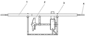
Accompanying drawing is the structural representation of the utility model.
Specific embodiment
Referring to accompanying drawing, the utility model is made up of two-part up and down, and top is a kickboard 1, and the bottom comprises impeller 2 and water pump 3, and both are continuous through a rotating shaft.Kickboard 1 both sides are provided with connecting head 4, during use, through kickboard 1 one sides rope are connected with the bank, are placed in the water again.Current make its rotation through impeller 2, drive water pump 3 work through rotating shaft again.On water pump 3, be provided with water outlet and water intake, water outlet can be as required.Select the pipe joint of corresponding size.
Claims (2)
1. suction engine is characterized in that: it is made up of two-part up and down, and top is a kickboard, and the bottom comprises impeller and water pump, and both are continuous through a rotating shaft; Said water pump is provided with water intake, water outlet.
2. a kind of suction engine according to claim 1 is characterized in that: said kickboard both sides also are provided with the rope joint.
Priority Applications (1)
| Application Number | Priority Date | Filing Date | Title |
|---|---|---|---|
| CN2011204423100U CN202326058U (en) | 2011-11-10 | 2011-11-10 | Water pumping device |
Applications Claiming Priority (1)
| Application Number | Priority Date | Filing Date | Title |
|---|---|---|---|
| CN2011204423100U CN202326058U (en) | 2011-11-10 | 2011-11-10 | Water pumping device |
Publications (1)
| Publication Number | Publication Date |
|---|---|
| CN202326058U true CN202326058U (en) | 2012-07-11 |
Family
ID=46438040
Family Applications (1)
| Application Number | Title | Priority Date | Filing Date |
|---|---|---|---|
| CN2011204423100U Expired - Fee Related CN202326058U (en) | 2011-11-10 | 2011-11-10 | Water pumping device |
Country Status (1)
| Country | Link |
|---|---|
| CN (1) | CN202326058U (en) |
Cited By (1)
| Publication number | Priority date | Publication date | Assignee | Title |
|---|---|---|---|---|
| CN105065288A (en) * | 2015-09-08 | 2015-11-18 | 湘潭大学 | Small-sized water pumping device using flowing water kinetic energy |
-
2011
- 2011-11-10 CN CN2011204423100U patent/CN202326058U/en not_active Expired - Fee Related
Cited By (1)
| Publication number | Priority date | Publication date | Assignee | Title |
|---|---|---|---|---|
| CN105065288A (en) * | 2015-09-08 | 2015-11-18 | 湘潭大学 | Small-sized water pumping device using flowing water kinetic energy |
Similar Documents
| Publication | Publication Date | Title |
|---|---|---|
| CN102536611A (en) | High-efficient sea wave power generation device | |
| CN202326058U (en) | Water pumping device | |
| CN203201741U (en) | Pump combination of movable type water injection system | |
| CN201763623U (en) | Self-priming water driven pump | |
| CN204511793U (en) | A kind of low water head energy collecting device | |
| CN201723378U (en) | Wind-water combined generation device | |
| CN203321859U (en) | Low-lift bidirectional vertical shaft tubular pump device | |
| CN201412259Y (en) | Power generation device of water turbine | |
| CN204704080U (en) | Water pump pressurizing device | |
| CN203627256U (en) | Submersible electric pump capable of lowering shutdown water level | |
| CN203670168U (en) | Micro water head fluid-energy water pumping system | |
| CN103591004B (en) | A kind of micro-head fluid energy pumping system | |
| CN201225223Y (en) | Hydroelectric generator | |
| CN202946300U (en) | Water pumping regeneration electricity generation device | |
| CN202215481U (en) | Wind-driven water pump | |
| CN202954917U (en) | Device utilizing sewer pipe current to generate electricity | |
| CN202971224U (en) | Hydraulic power experimental apparatus for axial flow pump | |
| CN201661513U (en) | Pump reverse turbo wheel inlet | |
| CN204371761U (en) | A kind of micro-resistance impeller for chemical centrifugal pump | |
| CN203362545U (en) | Centrifugal pump water-pumping device with vacuum water tank | |
| CN205315221U (en) | Device for lifting irrigation with wind energy | |
| CN203452978U (en) | Wind energy and solar energy supplementary power generation system | |
| CN204738974U (en) | High efficiency single stage pump | |
| CN102734140B (en) | Piezoelectric pump and its pipe arrangement | |
| CN202176519U (en) | Multifunctional pressure-boost integrated pump for double-barrel solar water heater |
Legal Events
| Date | Code | Title | Description |
|---|---|---|---|
| C14 | Grant of patent or utility model | ||
| GR01 | Patent grant | ||
| CF01 | Termination of patent right due to non-payment of annual fee | ||
| CF01 | Termination of patent right due to non-payment of annual fee |
Granted publication date: 20120711 Termination date: 20171110 |