CN202310598U - Double-conveying maize harvesting machine - Google Patents
Double-conveying maize harvesting machine Download PDFInfo
- Publication number
- CN202310598U CN202310598U CN2011204428301U CN201120442830U CN202310598U CN 202310598 U CN202310598 U CN 202310598U CN 2011204428301 U CN2011204428301 U CN 2011204428301U CN 201120442830 U CN201120442830 U CN 201120442830U CN 202310598 U CN202310598 U CN 202310598U
- Authority
- CN
- China
- Prior art keywords
- delivery chute
- conveying
- harvesting machine
- maize harvesting
- double
- Prior art date
- Legal status (The legal status is an assumption and is not a legal conclusion. Google has not performed a legal analysis and makes no representation as to the accuracy of the status listed.)
- Expired - Fee Related
Links
Images
Abstract
The utility model relates to agricultural harvesting machines and particularly relates to a double-conveying maize harvesting machine. The double-conveying maize harvesting machine comprises a traveling mechanism, a cutting table mounted at the front end of the traveling mechanism, a granary mounted at the rear end of the traveling mechanism and conveying troughs mounted between the cutting table and the granary, wherein the traveling mechanism comprises a frame, traveling wheels arranged below the frame and a driving cab arranged on the frame. The double-conveying maize harvesting machine is characterized in that the conveying troughs comprise a left conveying trough and a left conveying trough which are respectively mounted on the frame; and inlet ends of the left conveying trough and the right conveying trough are respectively connected to the left side and the right side of the cutting table. According to the double-conveying maize harvesting machine, two sets of conveying troughs, namely the left conveying trough and the right conveying trough are used, so that augers with complex structures and easiness for blocking are omitted, and further the production efficiency is increased and the fault rate is reduced; and in addition, output ports of the two sets of conveying troughs are respectively arranged on two sides of a stripping mechanism, so that maize cobs are uniformly distributed and the improvement on the stripping efficiency and the stripping effect is facilitated.
Description
Technical field
The utility model relates to a kind of agricultural harvesting machinery, is that maize harvesting machine is sent in a kind of lose-lose specifically.
Background technology
Existing propelled type maize harvesting machine comprises running gear, harvesting mechanism, peeling procedure and silo.Harvesting mechanism is usually located at the front end of running gear, and peeling procedure and silo are positioned at the rear end of running gear, gathers between the peeling procedure, silo of mechanism and rear end to be connected through delivery chute, and the maize cob of gathering in is sent to the rear end.The delivery chute of existing maize harvesting machine mostly is arranged on a side of running gear; The left side or the right; Because the fabric width of harvesting mechanism is bigger; The porch that screw feeder just can focus on the maize cob of harvesting delivery chute need be set,, be easy to during conveying stop up because inlet is wide, delivery chute is narrow; In addition, in the exit of delivery chute, because the maize cob of input is too concentrated, the peeling efficient and the peeling effect of peeling procedure all are affected.
Summary of the invention
The purpose of the utility model provide a kind of simple in structure, be not easy blocking channel, maize harvesting machine is sent in the lose-lose good, that fault rate is low of peeling treatment effect.
The utility model is that the technical scheme that the technical solution problem is adopted is:
The described lose-lose of the utility model send maize harvesting machine comprise running gear, be installed in the running gear front end the ceding of Taiwan, be installed in the running gear rear end silo, be arranged on the delivery chute between the ceding of Taiwan and the silo; Said running gear comprises vehicle frame and is arranged on road wheel below the vehicle frame, is arranged on the driver's cabin above the vehicle frame; It is characterized in that: said delivery chute comprises left delivery chute and right delivery chute; Left side delivery chute and right delivery chute are installed in above the vehicle frame, and the arrival end of left delivery chute and right delivery chute is connected respectively to the and arranged on left and right sides of the ceding of Taiwan.
Between delivery chute and silo, be provided with peeling procedure, the port of export of left delivery chute and right delivery chute is separately positioned on the and arranged on left and right sides of peeling procedure.
The arrival end of a left side delivery chute and right delivery chute is connected corresponding conveyer belt respectively, said conveyer belt be arranged on the ceding of Taiwan below.
Because two cover delivery chutes about having adopted said structure, lose-lose to send maize harvesting machine to adopt have saved the screw feeder that complex structure, easy generation are stopped up, and have improved efficiency, have reduced fault rate; In addition, the delivery outlet of two cover delivery chutes is separately positioned on the both sides of peeling procedure, and maize cob is shared evenly, helps improving the efficient and the peeling effect of peeling.
Description of drawings
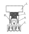
Fig. 1 is the structural representation of an embodiment of the utility model.
Fig. 2 is the vertical view of Fig. 1 embodiment.
Embodiment
As shown in the figure; The described lose-lose of the utility model send maize harvesting machine comprise running gear 1, be installed in running gear 1 front end the ceding of Taiwan 2, be installed in running gear 1 rear end silo 3, be arranged on the delivery chute 4 between the ceding of Taiwan 2 and the silo 3, be provided with the track-mounted conveyer belt in the delivery chute 4.Said running gear 1 comprises vehicle frame and is arranged on road wheel 11 below the vehicle frame, is arranged on the driver's cabin 12 above the vehicle frame; Said delivery chute 4 comprises left delivery chute 41 and right delivery chute 42; Left side delivery chute 41 is installed in above the vehicle frame with right delivery chute 42, and the arrival end of left delivery chute 41 and right delivery chute 42 is connected respectively to the and arranged on left and right sides of the ceding of Taiwan 2.The said ceding of Taiwan 2 has multiple structure available, and its concrete structure need not enumeration.Can use 4 row to reach following reaping corn devices, also can use 6 row or 8 row reaping corn devices, the left and right half range of the left delivery chute 41 and the corresponding ceding of Taiwan of right delivery chute 42 difference.
If do not need peeling, can be directly the port of export of left delivery chute 41 and right delivery chute 42 be connected to silo 3.Peeling if desired, as shown in Figure 2, between delivery chute 4 and silo 3, be provided with peeling procedure 5, the port of export of left delivery chute 41 and right delivery chute 42 is separately positioned on the and arranged on left and right sides of peeling procedure 5.
The arrival end of a left side delivery chute 41 and right delivery chute 42 is connected the conveyer belt 43 of correspondence respectively, said conveyer belt 43 be arranged on the ceding of Taiwan 2 below.
During work, the maize cob that the ceding of Taiwan 2 is taken off drops on the conveyer belt 43, is sent to left delivery chute 41 or right delivery chute 42 through conveyer belt 43, is transported to peeling procedure 5, and peeling gets into silo 3 later on.
The concrete structure of peeling procedure 5 and conveyer belt 43 is a known technology, does not do detailed description at this.
Claims (3)
1. maize harvesting machine is sent in lose-lose; Comprise running gear (1), be installed in running gear (1) front end the ceding of Taiwan (2), be installed in running gear (1) rear end silo (3), be arranged on the delivery chute (4) between the ceding of Taiwan (2) and the silo (3); Said running gear (1) comprises vehicle frame and is arranged on road wheel (11) below the vehicle frame, is arranged on the driver's cabin (12) above the vehicle frame; It is characterized in that: said delivery chute (4) comprises left delivery chute (41) and right delivery chute (42); Left side delivery chute (41) and right delivery chute (42) are installed in above the vehicle frame, and the arrival end of left delivery chute (41) and right delivery chute (42) is connected respectively to the and arranged on left and right sides of the ceding of Taiwan (2).
2. maize harvesting machine is sent in lose-lose according to claim 1; It is characterized in that: between delivery chute (4) and silo (3), be provided with peeling procedure (5), the port of export of left delivery chute (41) and right delivery chute (42) is separately positioned on the and arranged on left and right sides of peeling procedure (5).
3. maize harvesting machine is sent in lose-lose according to claim 1 and 2, it is characterized in that: the arrival end of left delivery chute (41) and right delivery chute (42) is connected corresponding conveyer belt (43) respectively, said conveyer belt (43) be arranged on the ceding of Taiwan (2) below.
Priority Applications (1)
| Application Number | Priority Date | Filing Date | Title |
|---|---|---|---|
| CN2011204428301U CN202310598U (en) | 2011-11-10 | 2011-11-10 | Double-conveying maize harvesting machine |
Applications Claiming Priority (1)
| Application Number | Priority Date | Filing Date | Title |
|---|---|---|---|
| CN2011204428301U CN202310598U (en) | 2011-11-10 | 2011-11-10 | Double-conveying maize harvesting machine |
Publications (1)
| Publication Number | Publication Date |
|---|---|
| CN202310598U true CN202310598U (en) | 2012-07-11 |
Family
ID=46422615
Family Applications (1)
| Application Number | Title | Priority Date | Filing Date |
|---|---|---|---|
| CN2011204428301U Expired - Fee Related CN202310598U (en) | 2011-11-10 | 2011-11-10 | Double-conveying maize harvesting machine |
Country Status (1)
| Country | Link |
|---|---|
| CN (1) | CN202310598U (en) |
Cited By (1)
| Publication number | Priority date | Publication date | Assignee | Title |
|---|---|---|---|---|
| CN107258238A (en) * | 2017-06-14 | 2017-10-20 | 合肥市禾兴生态养殖科技有限公司 | The conveying device of maize harvesting machine three |
-
2011
- 2011-11-10 CN CN2011204428301U patent/CN202310598U/en not_active Expired - Fee Related
Cited By (1)
| Publication number | Priority date | Publication date | Assignee | Title |
|---|---|---|---|---|
| CN107258238A (en) * | 2017-06-14 | 2017-10-20 | 合肥市禾兴生态养殖科技有限公司 | The conveying device of maize harvesting machine three |
Similar Documents
| Publication | Publication Date | Title |
|---|---|---|
| CN106717593B (en) | Tangential longitudinal flow threshing and separating device | |
| CN202931803U (en) | Header of corn harvester | |
| CN104160824B (en) | A kind of transmission system of cutting crossing current multiple-roll combine | |
| CN203136483U (en) | Seeder | |
| CN202310598U (en) | Double-conveying maize harvesting machine | |
| CN103416155B (en) | A kind of sugar-cane cutting machine | |
| CN203801319U (en) | Harvester elevator feeding port cover plate structure | |
| CN203378284U (en) | Hinged feeding and conveying trough structure in combined harvester | |
| CN201374923Y (en) | Cut-off feeding device of cane harvester | |
| CN203243712U (en) | Semi-feeding combine-harvester cutting table | |
| CN102884913B (en) | A kind of maize harvesting machine and the ceding of Taiwan thereof | |
| CN205196341U (en) | Corn husker fruit ear feeding device and corn combine | |
| CN207543672U (en) | A kind of gettering formula seed cleaning device and harvest machinery | |
| CN103004364A (en) | Multifunctional harvesting machine | |
| CN204350644U (en) | A kind of maize harvesting machine | |
| CN203435369U (en) | Harvesting and cleaning machine | |
| CN205005512U (en) | Corn thresher from loading attachment | |
| CN208724417U (en) | A kind of new type maize harvesting machine stalk delivery chute | |
| CN202799660U (en) | Combine harvester with double-spiral auger conveying grain mechanism | |
| CN204031815U (en) | A kind of transmission system of cutting crossing current multiple-roll combine | |
| CN202873348U (en) | Maize harvesting machine and header | |
| CN203590721U (en) | Hand-operated wheat combine harvester | |
| CN205266303U (en) | Header | |
| CN201123252Y (en) | Straw-arranging mechanism for maize harvesting machine | |
| CN105165247A (en) | Ear feeding device of corn husker and combined corn harvester |
Legal Events
| Date | Code | Title | Description |
|---|---|---|---|
| C14 | Grant of patent or utility model | ||
| GR01 | Patent grant | ||
| C17 | Cessation of patent right | ||
| CF01 | Termination of patent right due to non-payment of annual fee |
Granted publication date: 20120711 Termination date: 20121110 |