Outdoor case is used the ventilation hole protector
Technical field
The utility model relates to outdoor case and uses the ventilation hole protector, relates in particular to the protector of electrical system casings such as convergence control cabinet, distribution box, mechanism case with the ventilating opening place.
Background technology
The electrical system casing in use; As do not have the forced ventilation requirement, generally adopt ventilation hole to dispel the heat, take a breath, but after offering ventilation hole; Dust and little winged insect can get into box house from ventilation hole; Also have rainwater when rainy and get into box house, bring potential safety hazard so for the reliability service of the equipment in the casing from ventilation hole, so the ventilation hole protection object of attaching most importance to; The degree of protection of the above-mentioned casing of national Specification need reach IP54, so the degree of protection of ventilation hole protector also need reach the national standard of IP54.
Industry is to set up Air Filter for dustproof usual way at present; Usually the method that adopts for waterproof is to set up bucker; The Chinese patent notification number is CN201726049U; The day for announcing is on 01 26th, 2011; Name is called and discloses a kind of outdoor case in ' a kind of outdoor case use the ventilation hole protector ' specification and use the ventilation hole protector, comprises the protector housing that is used to be installed on the outdoor case and is positioned at the dustproof filter pad of protector enclosure interior, and this protector housing comprises bridging board, be positioned at the bridging board both sides and through continuous biside plate of bridging board and the side plate that is positioned at the bridging board rear end and links to each other with bridging board; The inboard of said bridging board, biside plate and side plate is configured for holding the cavity of dustproof filter pad, and said dustproof filter pad is spacing by the Stop structure of being located at the bridging board front end.But this ventilation hole protector can not reach the national standard of IP54, and Air Filter all is arranged on the bucker in this protector, and this structure is insecure, and ventilation effect is bad.Bucker normally is fixed on the casing with marine glue or water-proof sealing strip in addition; Because bucker is located at the casing outside; So marine glue or waterproof sealing adhesive tape are directly exposed to occurring in nature, ageing failure or be considered to destroy very easily, and then bucker and casing are damaged.
The utility model content
The purpose of the utility model is to provide outdoor case to use the ventilation hole protector, and is not enough with the degree of protection that solves ventilation and protection device in the prior art, install insecure, the problem that ventilation effect is bad.
For realizing above-mentioned purpose; The utility model adopts following technical scheme: outdoor case is used the ventilation hole protector, comprises shell, the biside plate that said shell comprises bridging board, is positioned at the bridging board both sides and links to each other through bridging board; Reach end plate with biside plate and bridging board back-end closure; Said bridging board is a rectangle, and shell front end spiral-lock has shell block, and said shell block is provided with and is used for the intercommunicating pore that is communicated with ventilation hole; Cavity between intercommunicating pore and shell and the shell block has constituted downward vent passages jointly, and shell block is provided with the Air Filter that is used for the intercommunicating pore sealing.
Vent passages bottom between shell and the shell block is provided with water-retaining structure.
Described water-retaining structure comprises the staggered outstanding water fender of establishing; A two adjacent water fenders end face separately is installed in respectively on the sidewall of each self-corresponding shell; The other end is tilted to down the center of stretching shell, and the both sides of water fender extend to respectively on the medial surface of end plate of shell block rear end face and shell.
Convex with in the below of water fender on the said shell block rear end face and be used for the support raised line that cooperates with the water fender side lap, the medial surface of the opposite side of water fender and the end plate of shell fixedly installs.
Convex with on the end plate medial surface of shell and be used for shell and shell block are fixed on the mounting boss on the casing, the corresponding said mounting boss of shell block position is provided with the assembling through hole.
Ring platform before said shell block front end face convexes with in the intercommunicating pore place and is used to be inserted in the casing ventilation hole; The endoporus front end of preceding ring platform is provided with Turbogrid plates; The shell block rear end face convexes with the back ring platform of internal diameter and intercommunicating pore equal diameters in the intercommunicating pore place; Said back ring platform inner chamber and intercommunicating pore have constituted the cavity that holds Air Filter jointly, and Air Filter is arranged in the said cavity.
The shell block front end face is equipped with seal groove in the outer peripheral face place of preceding ring platform, is provided with the waterproof grommet that is used for the cabinet exterior sealing in the seal groove.
The front end face of ring platform is provided with the screwed hole that is used to install fan before said.
Bridging board and end plate lateral surface junction are provided with the transition circle cambered surface.
The outer edge surface of the front end edge shell of shell convexes with eaves, and shell block has and is used for and the spacing outer edge surface that cooperates of the inner edge surface of said eaves, and the shell block buckle is in the eaves of shell.
The outdoor case of the utility model is used the ventilation hole protector, is provided with shell block between shell and the cabinet exterior, makes fixed structure more firm; Air Filter is installed on the shell block simultaneously, also makes the more firm of Air Filter installation, thereby prolongs the useful life of ventilation hole protector; Form cavity between shell block and the shell; The bridging board of the utility model is a rectangle, has increased draught area, reaches good ventilation effect.
Further, the outstanding interlaced water fender of establishing of outer casing underpart under the situation that does not increase the distance between shell lower ending opening and the ventilation hole, has prevented that effectively rainwater is splashed in the casing by vent passages.
Further, the downward-sloping angle of water fender free end, when effectively having prevented to dabble, aqueous reflux advances vent passages.Further; The shell block front end face is provided with the preceding ring platform of protrusion; Before the ring platform cooperates with the ventilation hole sleeve, better with the protector location and installation in the casing vent, the Turbogrid plates that are provided with in the hole of ring platform before simultaneously also with the Air Filter accurate localization intercommunicating pore and after encircle in the inner chamber of platform.
Further, the seal of shell block front end face setting does not need to be coated with fluid sealant around the shell in the prior art, prevents rainwater from connecting the casing of entering between the slit, and seal is arranged on shell block inside, is difficult for wearing out, and has prolonged the useful life of ventilation hole protector.
Description of drawings
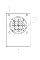
Fig. 1 is the front view of the shell block among the utility model embodiment 1;
Fig. 2 is the rearview of Fig. 1;
Fig. 3 is the AA cutaway view of Fig. 2;
Fig. 4 is the front view of the shell among the utility model embodiment 1;
Fig. 5 is the BB cutaway view of Fig. 4;
Fig. 6 is the assembling utilization structure sketch map of the utility model embodiment 1;
Fig. 7 is the front view of the shell block among the utility model embodiment 2;
Fig. 8 is the CC cutaway view of Fig. 7;
Fig. 9 is the front view of the shell among the embodiment 2 of the utility model;
Figure 10 is the DD cutaway view of Fig. 9;
Figure 11 is the assembling utilization structure sketch map of the utility model embodiment 2;
Figure 12 is the stereogram of the embodiment 2 of the utility model.
Embodiment
Outdoor case is with the embodiment 1 of ventilation hole protector, and like Fig. 1-shown in Figure 6, the shell 2 among this embodiment is shown in Fig. 4-5; Be the one-shot forming structure, it comprises that top is rectangular bridging board 24, the biside plate 25 that is positioned at the bridging board both sides and links to each other through bridging board; Reach the end plate 26 with biside plate and bridging board back-end closure, bridging board 24 is provided with transition arc with the end plate connecting place, and the outer edge surface of the front end edge shell of shell 2 convexes with eaves 27; End plate 26 medial surfaces of shell convex with four mounting boss 21, are provided with tapped blind hole 23 on the mounting boss 21, and the shell block in the present embodiment is shown in Fig. 1-3; This shell block 1 has the outer edge surface that the inner edge surface shape with the eaves 27 of shell 2 is complementary; The position of the tapped blind hole 23 on the corresponding mounting boss 21 of shell block 1 first half is provided with assembling through hole 15, and shell block 1 is provided with and is used for the intercommunicating pore 14 that is communicated with the casing ventilation hole, convexes with the preceding ring platform 18 that is used to be inserted in the casing ventilation hole in intercommunicating pore 14 front ends on the shell block 1; The front end of the endoporus of preceding ring platform is installed with Turbogrid plates 12; Preceding ring platform 18 front end faces are provided with the screwed hole 17 that is used to install fan, and the shell block rear end face convexes with the back ring platform 16 of internal diameter and intercommunicating pore equal diameters in intercommunicating pore 14 places, and shell block 1 front end face is equipped with seal groove 11 in the outer peripheral face place of preceding ring platform 18; Present embodiment 1 in use; As shown in Figure 6, back ring platform 16 has Air Filter 3 with the inner chamber welding (or being threaded) of intercommunicating pore 14, and shell block 1 spiral-lock is in the eaves 27 of shell 2 front ends; Cavity between intercommunicating pore 14 and shell block 1 and the shell 2 has constituted downward vent passages jointly; Seal groove 11 on the shell block 1 has been embedded in waterproof grommet 5, and the preceding ring platform 18 on the shell block 1 is inserted in the ventilation hole of casing, and bolt 4 passes in the tapped blind hole 23 on the mounting boss 21 that assembling through hole 15 on casing and the shell block 1 is screwed into shell from cabinet wall; Shell block 1 and shell are connected the vent of casing, are provided with retaining spring shim 6 between screw 4 and the cabinet wall.
Outdoor case is with the embodiment 2 of ventilation hole protector, and shown in Fig. 7-12, the embodiment 2 of the utility model is with the difference of embodiment 1; Embodiment 2 is provided with water-retaining structure in the vent passages bottom between shell 2 and the shell block 1 on the basis based on the structure of shell among the embodiment 1 and shell block, said water-retaining structure comprises; Like Fig. 9-shown in Figure 10, three water fenders 22 that are crisscross arranged, two an adjacent water fenders end face separately is installed in respectively on the sidewall of each self-corresponding shell; The other end is tilted to down the center of stretching shell; Like Fig. 7-shown in Figure 8, staggered being provided with is used for the support raised line 13 that the lower edge face with water fender 22 matches to shell block 1 in the below of the position of the water fender 22 of corresponding shell 2, and a side of water fender is fixedly installed on the medial surface of end plate; The opposite side overlap joint is supporting on the raised line 13; When present embodiment used in assembling, shown in figure 11, water fender 22 overlap joints of shell 2 were on the support raised line 13 on the shell block 1.
In other embodiments, when assembling is used, can also not be embedded waterproof grommet on the shell block, around shell block and casing contact-making surface, be coated with waterproof gasket cement, reach sealing effectiveness and get final product.
In other embodiments; Described water-retaining structure can also be the two rows cylinder that between shell block and shell, staggers and be provided with; The improvement of the unsubstantiality that those skilled in the art carry out water-retaining structure on the basis of this design and technical scheme all drops within the protection range of the utility model.
In embodiment 2, the number of water fender is three, and those skilled in the art also can be arranged to two or four, but all drops within the protection range of the utility model.
In other embodiment, also can directly ventilate through intercommunicating pore, fan need be set.
In other embodiment, shell and shell block also can directly be welded on the cabinet exterior.