CN202308389U - Card connector - Google Patents
Card connector Download PDFInfo
- Publication number
- CN202308389U CN202308389U CN2011202228334U CN201120222833U CN202308389U CN 202308389 U CN202308389 U CN 202308389U CN 2011202228334 U CN2011202228334 U CN 2011202228334U CN 201120222833 U CN201120222833 U CN 201120222833U CN 202308389 U CN202308389 U CN 202308389U
- Authority
- CN
- China
- Prior art keywords
- terminal
- card connector
- insulating body
- circuit board
- connecting portion
- Prior art date
- Legal status (The legal status is an assumption and is not a legal conclusion. Google has not performed a legal analysis and makes no representation as to the accuracy of the status listed.)
- Expired - Fee Related
Links
Images


Classifications
-
- H—ELECTRICITY
- H01—ELECTRIC ELEMENTS
- H01R—ELECTRICALLY-CONDUCTIVE CONNECTIONS; STRUCTURAL ASSOCIATIONS OF A PLURALITY OF MUTUALLY-INSULATED ELECTRICAL CONNECTING ELEMENTS; COUPLING DEVICES; CURRENT COLLECTORS
- H01R13/00—Details of coupling devices of the kinds covered by groups H01R12/70 or H01R24/00 - H01R33/00
- H01R13/66—Structural association with built-in electrical component
- H01R13/665—Structural association with built-in electrical component with built-in electronic circuit
- H01R13/6658—Structural association with built-in electrical component with built-in electronic circuit on printed circuit board
-
- H—ELECTRICITY
- H01—ELECTRIC ELEMENTS
- H01R—ELECTRICALLY-CONDUCTIVE CONNECTIONS; STRUCTURAL ASSOCIATIONS OF A PLURALITY OF MUTUALLY-INSULATED ELECTRICAL CONNECTING ELEMENTS; COUPLING DEVICES; CURRENT COLLECTORS
- H01R12/00—Structural associations of a plurality of mutually-insulated electrical connecting elements, specially adapted for printed circuits, e.g. printed circuit boards [PCB], flat or ribbon cables, or like generally planar structures, e.g. terminal strips, terminal blocks; Coupling devices specially adapted for printed circuits, flat or ribbon cables, or like generally planar structures; Terminals specially adapted for contact with, or insertion into, printed circuits, flat or ribbon cables, or like generally planar structures
- H01R12/70—Coupling devices
- H01R12/7005—Guiding, mounting, polarizing or locking means; Extractors
- H01R12/7011—Locking or fixing a connector to a PCB
- H01R12/707—Soldering or welding
-
- H—ELECTRICITY
- H01—ELECTRIC ELEMENTS
- H01R—ELECTRICALLY-CONDUCTIVE CONNECTIONS; STRUCTURAL ASSOCIATIONS OF A PLURALITY OF MUTUALLY-INSULATED ELECTRICAL CONNECTING ELEMENTS; COUPLING DEVICES; CURRENT COLLECTORS
- H01R12/00—Structural associations of a plurality of mutually-insulated electrical connecting elements, specially adapted for printed circuits, e.g. printed circuit boards [PCB], flat or ribbon cables, or like generally planar structures, e.g. terminal strips, terminal blocks; Coupling devices specially adapted for printed circuits, flat or ribbon cables, or like generally planar structures; Terminals specially adapted for contact with, or insertion into, printed circuits, flat or ribbon cables, or like generally planar structures
- H01R12/70—Coupling devices
- H01R12/71—Coupling devices for rigid printing circuits or like structures
- H01R12/712—Coupling devices for rigid printing circuits or like structures co-operating with the surface of the printed circuit or with a coupling device exclusively provided on the surface of the printed circuit
- H01R12/714—Coupling devices for rigid printing circuits or like structures co-operating with the surface of the printed circuit or with a coupling device exclusively provided on the surface of the printed circuit with contacts abutting directly the printed circuit; Button contacts therefore provided on the printed circuit
-
- H—ELECTRICITY
- H01—ELECTRIC ELEMENTS
- H01R—ELECTRICALLY-CONDUCTIVE CONNECTIONS; STRUCTURAL ASSOCIATIONS OF A PLURALITY OF MUTUALLY-INSULATED ELECTRICAL CONNECTING ELEMENTS; COUPLING DEVICES; CURRENT COLLECTORS
- H01R27/00—Coupling parts adapted for co-operation with two or more dissimilar counterparts
-
- H—ELECTRICITY
- H01—ELECTRIC ELEMENTS
- H01R—ELECTRICALLY-CONDUCTIVE CONNECTIONS; STRUCTURAL ASSOCIATIONS OF A PLURALITY OF MUTUALLY-INSULATED ELECTRICAL CONNECTING ELEMENTS; COUPLING DEVICES; CURRENT COLLECTORS
- H01R12/00—Structural associations of a plurality of mutually-insulated electrical connecting elements, specially adapted for printed circuits, e.g. printed circuit boards [PCB], flat or ribbon cables, or like generally planar structures, e.g. terminal strips, terminal blocks; Coupling devices specially adapted for printed circuits, flat or ribbon cables, or like generally planar structures; Terminals specially adapted for contact with, or insertion into, printed circuits, flat or ribbon cables, or like generally planar structures
- H01R12/50—Fixed connections
- H01R12/59—Fixed connections for flexible printed circuits, flat or ribbon cables or like structures
- H01R12/592—Fixed connections for flexible printed circuits, flat or ribbon cables or like structures connections to contact elements
Landscapes
- Engineering & Computer Science (AREA)
- Microelectronics & Electronic Packaging (AREA)
- Coupling Device And Connection With Printed Circuit (AREA)
- Combinations Of Printed Boards (AREA)
Abstract
The utility model discloses a card connector. The card connector includes an insulation body, terminals fixed on the insulation body, a flexible printed circuit board and a changeover module. The insulation body is provided with an accommodation room having a front opening. Each of the terminals includes a contact part protruding into the accommodation room and a connection part extending outside the insulation body. The connection parts of the terminals are arranged in at least two rows. The flexible printed circuit board is provided with an input terminal and an output terminal together connecting with the connection parts. The changeover module also includes a changeover terminal connected to the output terminal of the flexible printed circuit board and a welding terminal extending outside the changeover module. The flexibility of the flexible printed circuit board facilitates the card connector to meet a requirement of copanarity.
Description
[technical field]
The utility model relates to a kind of card connector, relates in particular to a kind of card connector with flexible printed circuit board.
[background technology]
Card connector can be used to expand the for example function of electronic product such as computer or digital camera usually.Nowadays, various card connector is developed to be used to accommodate existing diversified storage card.Be provided with the terminal that electrically contacts with corresponding storage card in the common this card connector.Yet; Card connector extends the corresponding position that insulating body is installed in circuit board through the terminal weld part; Because the weld part quantity of terminal is more in the card connector, and card connector miniaturization day by day, the correspondence position that the terminal weld part that guarantee One's name is legion is positioned at circuit board simultaneously is difficulty relatively; The coplane degree that is card connector is difficult to be guaranteed, and may influence the signal transmission of card connector.
So, be necessary to design a kind of new structure to improve the problems referred to above.
[utility model content]
The utility model technical problem to be solved is to provide a kind of weld part that helps terminal accurately to be welded in the card connector of the correspondence position of circuit board.
For addressing the above problem; The utility model adopts following technical scheme: a kind of card connector; Has a butt joint direction; Said card connector comprises insulating body, is immobilizated in the terminal of insulating body, flexible printed circuit board and interconnecting module; Said insulating body is provided with the receiving space of a front opening, and each terminal comprises contact site that protrudes into receiving space and the connecting portion that extends insulating body, and the connecting portion of said terminal is arranged in two rows at least; Said flexible printed circuit board is provided with input and the output that connects said connecting portion, and said interconnecting module comprises change-over terminal that is connected in the flexible printed circuit board output and the welding ends that extends interconnecting module.
Compared with prior art, the utlity model has following beneficial effect: flexible printed circuit board is set on insulating body, the flexibility that this flexible printed circuit board has helps the demand that card connector is reached coplane degree.
[description of drawings]
Fig. 1 is the stereogram of the utility model card connector;
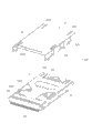
Fig. 2 lid shown in Figure 1 and card connector separated portions three-dimensional exploded view;
Fig. 3 is that the terminal module of the utility model card connector is from the body separated portions exploded view that insulate;
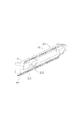
Fig. 4 is the stereogram of another angle of card connector shown in Figure 1;
Fig. 5 is that shielding casing shown in Figure 4 is from card connector separated portions exploded view;
Fig. 6 is the part exploded view of card connector shown in Figure 4;
Fig. 7 is the stereogram of the switching module of the utility model card connector.
[embodiment]
Please join Fig. 1, Fig. 2 and Fig. 5, this creation card connector 100 comprises insulating body 1, be immobilizated in terminal on the insulating body 1, be arranged at treadmill 8, retreat-card device in the insulating body 1, be installed on insulating body 1 lid 2, be immobilizated in insulating body 1 interconnecting module 3, be covered in shielding casing 4 and flexible printed circuit board 9 on the insulating body 1.
Please join Fig. 2, Fig. 3 and shown in Figure 6; Said insulating body 1 extends rectangular setting along the butt joint direction; This insulating body 1 comprises diapire 113, first end wall 111 and second end wall 112; Said first end wall 111 and second end wall 112 are located at diapire 113 two ends relatively, and first end wall 111, second end wall 112 and diapire 113 form the receiving space 11 of upward opening in the butt joint direction.Diapire 113 comprises that anterior 12 reach the rear portion 13 that on the butt joint direction, is oppositely arranged with front portion 12.Said insulating body 1 further comprises first surface 14 and the second surface 16 that is oppositely arranged.
Please join Fig. 2 to shown in Figure 6; Said terminal comprises the first terminal 51 that is immobilizated on the said insulating body 1 and is located at second terminal 52 and the 3rd terminal 53 on the terminal module 10; Said the first terminal 51 is arranged at the front portion 12 of diapire 113 and arranges side by side; Each the first terminal 51 comprises first connecting portion 512 that extends diapire 113 and first contact site 511 that extends back from first connecting portion 512; Said first contact site 511 is exposed to receiving space 11 electrically contacting with first electronic cards, and definition butt joint direction is a first direction, and said first connecting portion 512 is two rows along first direction and is oppositely arranged forwardly on 12.
The 3rd terminal 53 is assembled on the rear portion 13 of insulator 101; Said each the 3rd terminal 53 comprises the 3rd connecting portion 532 that extends said diapire 113 and the 3rd contact site 531 that extends forward from the 3rd connecting portion 532, and said the 3rd contact site 531 is exposed to receiving space 11 electrically to contact with the 3rd electronic cards.
Said terminal module 10 is installed on the said rear portion 13, and this terminal module 10 comprises the insulator 101 that is assembled in the insulating body 1 and is shaped in second terminal 52 in insulator 101 the place aheads.Said second terminal 52 is positioned at the place ahead of the 3rd terminal 53; This second terminal 52 comprises second connecting portion 522 that extends diapire 113 and second contact site 521 that extends forward from second connecting portion 522; This second contact site 521 is exposed to receiving space 11 electrically to contact with second electronic cards, and said second contact site 521 is oppositely arranged with said first contact site 511.The contact site of said first, second, third terminal protrudes into receiving space 11 respectively, and said first, second, third connecting portion extends receiving space 11 respectively and stretches out second surface 16.Said second connecting portion 522 and the 3rd connecting portion 532 each interval row on second direction establish, said second direction with dock direction and be positioned at same plane, and with dock that direction and vertical direction are vertical to be provided with.
Said treadmill 8 be installed in the receiving space 11 and anterior 12 and rear portion 13 between and this treadmill 8 can receiving space 11 in, move along docking direction; This treadmill 8 is provided with second terminal containing slot 81 of accommodating second contact site 521; One end of treadmill 8 is provided with projection 82; When second electronic cards is inserted receiving space 11; The front-end edge of second electronic cards pushes said projection 82 and the treadmill 8 that is provided with second terminal containing slot 81 is moved backward, and second terminal containing slot 81 pushes second contact site 521, second contact site 521 is moved on the vertical direction perpendicular to the butt joint direction and finally reaches electrical the contact with second electronic cards.
Said retreat-card device is located at the relative both sides of receiving space 11; This retreat-card device comprises first retreat-card device and second retreat-card device; Said first retreat-card device is arranged between first end wall 111 and the rear portion 13, and this first retreat-card device comprises first slide block 61 and connects first end wall 111 and first elastic component 71 of first slide block 61.First slide block 61 is arranged to the L type and has protrude into the 3rd of receiving space 11 and keep out face 611, and the said the 3rd keeps out face 611 keeps out in the 3rd electronic cards along the butt joint directions.Second retreat-card device is arranged between second end wall 112 and anterior 12, and this second retreat-card device comprises second slide block 62 and connects second end wall 112 and second elastic component 72 of second slide block 62.Second slide block 62 forms first and keeps out face 621 and second and keep out face 622 on the butt joint direction, said first keeps out face 621 and second keeps out face 622 and be respectively applied for and keep out first electronic cards and second electronic cards.
After said terminal module 10, treadmill 8 and retreat-card device are assembled in the said insulating body 1 successively; Said lid 2 is installed on downwards on the said insulating body 1 from the vertical direction perpendicular to said butt joint direction; And block on said first surface 14, so that retreat-card device is positioned at receiving space 11.
Please join Fig. 4 and shown in Figure 6; Said flexible printed circuit board 9 is provided with the part that is the Y type; This flexible printed circuit board 9 comprises and is used for respectively corresponding first installing hole 91 of accommodating first connecting portion 512, second connecting portion 522 and the 3rd connecting portion 532 that this first installing hole 91 forms the input of said flexible printed circuit board 9.Said flexible printed circuit board 9 comprises that also being in-line arranges second installing hole 92 of being located at flexible printed circuit board 9 edges, and this second installing hole 92 forms the output of said flexible printed circuit board 9.Said input and output are reached electric connection through the conducting wire that row is located on the flexible printed circuit board 9.Flexible printed circuit board 9 is installed on insulating body and is covered on the second surface 16; Said first connecting portion 512, second connecting portion 522 and the 3rd connecting portion 532 correspondences are contained in first installing hole 91 of said flexible printed circuit board 9; Because flexible printed circuit board 9 has certain flexibility; First connecting portion 512, second connecting portion 522 and the 3rd connecting portion 532 these flexibilities capable of using are relatively easy to be installed in first installing hole 91, thereby first connecting portion, second connecting portion and the 3rd connecting portion are installed accurately.
Said shielding casing 4 comprises the pair of sidewalls 42 that main part 41 and autonomous body 41 extend vertically downward, is respectively equipped with protuberance 15 on said first end wall 111 and second end wall 112, and said sidewall 42 is provided with the window portion 421 of this protuberance 15 of snap close.Said shielding casing 4 is installed on the second surface 16 of insulating body 1 flexible printed circuit board 9 is fixed on this insulating body 1; Said shielding casing 4 is provided with slot to make way 422 and accommodates first connecting portion 512 and second connecting portion 522 with correspondence, and makes first connecting portion 512 and second connecting portion 522 separate setting with shielding casing 4.The 3rd connecting portion 532 and switching part 33 are positioned at main part 41 rears and do not contact with shielding casing 4.
Please join shown in Figure 7; Said interconnecting module 3 comprises base portion 31 and is immobilizated in the conversion terminal of base portion 31; Said conversion terminal comprises switching part 33 and extends the weld part 32 of base portion 31; Said switching part 33 is connected in the output of said flexible printed circuit board 9, and this switching part 33 promptly forms said change-over terminal, and weld part 32 forms welding ends.Said base portion 31 is stretched towards a pleurapophysis of insulating body 1 and is provided with latch part 311, and said latch part 311 further is extended with the holding part 312 that is held in said insulating body 1 downwards.Said interconnecting module 3 is installed on the rear portion 13 of insulating body 1, and said holding part 312 is held in holding hole 132, and said weld part 32 and switching part 33 lay respectively at the relative both sides of insulating body 1, and switching part 33 stretches out second surface 16.Switching part 33 correspondences are contained in second installing hole 92, and promptly flexible printed circuit board 9 will be connected in the first terminal 51, second terminal 52 and the 3rd terminal 53 and the conversion terminal electric connection that is connected in output of input.
First installing hole 91 of flexible printed circuit board 9 in the utility model card connector; It is input; Corresponding with the first terminal 51, second terminal 52 and the 3rd terminal 53 first connecting portion 512, second connecting portion 522 and the 3rd connecting portion 532 are connected said second installing hole 92, the i.e. output; Be connected with the switching part 33 of conversion terminal, reach the electric connection between interconnecting module 3 and each terminal.The weld part 32 of said interconnecting module 3 is arranged in a row; And when the setting of this flexible printed circuit board 9 can supply that this card connector 100 is installed on the external circuit board weld part 32 is regulated; Make weld part 32 correspondences be arranged at the tram of the external circuit board, the weld part 32 that helps card connector reaches the demand of coplane degree.Interconnecting module 3 is installed on through locker and makes in the insulating body 1 that card connector is an overall appearance.
Above-mentioned execution mode is the utility model preferred embodiments, and the utility model also can adopt other execution mode certainly, gives unnecessary details no longer one by one here.
Claims (9)
1. card connector; Has a butt joint direction; Said card connector comprises insulating body, is immobilizated in the terminal of insulating body, flexible printed circuit board and interconnecting module; Said insulating body is provided with the receiving space of a front opening, and each terminal comprises contact site that protrudes into receiving space and the connecting portion that extends insulating body, and the connecting portion of said terminal is arranged in two rows at least; Said flexible printed circuit board is provided with input and the output that connects said connecting portion, and it is characterized in that: said interconnecting module comprises change-over terminal that is connected in the flexible printed circuit board output and the welding ends that extends interconnecting module.
2. card connector as claimed in claim 1; It is characterized in that: said interconnecting module comprises base portion and is immobilizated in the conversion terminal of base portion; Conversion terminal comprises switching part and extends the weld part of base portion that this switching part promptly forms said change-over terminal, weld part formation welding ends.
3. card connector as claimed in claim 2 is characterized in that: said base portion stretches out latch part in the pleurapophysis in the face of insulating body, and this latch part is held in said insulating body.
4. card connector as claimed in claim 3 is characterized in that: said interconnecting module is installed on the insulating body rear portion, and said weld part and switching part lay respectively at the relative both sides of insulating body.
5. card connector as claimed in claim 4; It is characterized in that: this card connector further comprises a shielding casing; Said shielding casing is installed on the insulating body flexible printed circuit board being fixed on this insulating body, and this shielding casing is provided with the slot to make way that the connecting portion that supplies terminal passes through.
6. card connector as claimed in claim 5; It is characterized in that: said card connector is used to accommodate first electronic cards, second electronic cards and the 3rd electronic cards; This card connector further comprises first retreat-card device and second retreat-card device of being located at the relative both sides of said receiving space; Said first retreat-card device is provided with keeps out the 3rd of the 3rd electronic cards and keeps out face, and said second retreat-card device is provided with first, second of keeping out first, second electronic cards respectively and keeps out face.
7. card connector as claimed in claim 1 is characterized in that: said insulating body is along the extension of butt joint direction and be provided with first surface and the second surface that is oppositely arranged, and said flexible printed circuit board is positioned at this second surface.
8. card connector as claimed in claim 7 is characterized in that: said card connector further comprises shielding casing, and this shielding casing is installed on the second surface of said insulating body, and said flexible printed circuit board is between shielding casing and insulating body.
9. card connector as claimed in claim 8; It is characterized in that: said terminal comprises the first terminal, second terminal and the 3rd terminal; Said the first terminal is provided with first connecting portion, and said second terminal is provided with second connecting portion, this card connector have with dock direction and vertical direction vertical and with dock direction and be positioned at the second direction on same plane; Said first connecting portion is arranged along the butt joint direction, and second connecting portion is arranged along second direction.
Applications Claiming Priority (2)
| Application Number | Priority Date | Filing Date | Title |
|---|---|---|---|
| US12/826703 | 2010-06-30 | ||
| US12/826,703 US7950964B1 (en) | 2010-06-30 | 2010-06-30 | N-IN-1 card connector utilizing FPC for improved co-planarity |
Publications (1)
| Publication Number | Publication Date |
|---|---|
| CN202308389U true CN202308389U (en) | 2012-07-04 |
Family
ID=44064051
Family Applications (1)
| Application Number | Title | Priority Date | Filing Date |
|---|---|---|---|
| CN2011202228334U Expired - Fee Related CN202308389U (en) | 2010-06-30 | 2011-06-29 | Card connector |
Country Status (3)
| Country | Link |
|---|---|
| US (1) | US7950964B1 (en) |
| CN (1) | CN202308389U (en) |
| TW (1) | TWM425428U (en) |
Cited By (1)
| Publication number | Priority date | Publication date | Assignee | Title |
|---|---|---|---|---|
| WO2024193531A1 (en) * | 2023-03-21 | 2024-09-26 | 杭州先途电子有限公司 | Detection device |
Families Citing this family (2)
| Publication number | Priority date | Publication date | Assignee | Title |
|---|---|---|---|---|
| US9236681B2 (en) * | 2014-03-21 | 2016-01-12 | Cheng Uei Precision Industry Co., Ltd. | Card connector |
| JP1524672S (en) * | 2014-10-13 | 2015-06-01 |
Family Cites Families (6)
| Publication number | Priority date | Publication date | Assignee | Title |
|---|---|---|---|---|
| TW452235U (en) * | 2000-09-29 | 2001-08-21 | Hon Hai Prec Ind Co Ltd | Connection device of electronic card |
| US7175477B2 (en) * | 2004-01-02 | 2007-02-13 | Chou Hsuan Tsai | Multi-card connector assembly having a modularized and flexible connection interface |
| TWI239687B (en) * | 2004-01-07 | 2005-09-11 | Top Yang Technology Entpr Co | Electronic card shared connector with moving range |
| TWM261852U (en) * | 2004-08-17 | 2005-04-11 | Molex Taiwan Ltd | Electrical connector |
| US7399186B2 (en) * | 2004-12-31 | 2008-07-15 | Chou Hsuan Tsai | Multi-card connector assembly having a modularized and flexible connection interface |
| TWI358161B (en) * | 2007-07-24 | 2012-02-11 | Hon Hai Prec Ind Co Ltd | Electrical card connector |
-
2010
- 2010-06-30 US US12/826,703 patent/US7950964B1/en not_active Expired - Fee Related
-
2011
- 2011-06-27 TW TW100211655U patent/TWM425428U/en not_active IP Right Cessation
- 2011-06-29 CN CN2011202228334U patent/CN202308389U/en not_active Expired - Fee Related
Cited By (1)
| Publication number | Priority date | Publication date | Assignee | Title |
|---|---|---|---|---|
| WO2024193531A1 (en) * | 2023-03-21 | 2024-09-26 | 杭州先途电子有限公司 | Detection device |
Also Published As
| Publication number | Publication date |
|---|---|
| TWM425428U (en) | 2012-03-21 |
| US7950964B1 (en) | 2011-05-31 |
Similar Documents
| Publication | Publication Date | Title |
|---|---|---|
| CN201397899Y (en) | Electric connector | |
| CN201160164Y (en) | Electric Connector | |
| CN201608308U (en) | Electric connector | |
| CN104733911B (en) | Electric connector combination | |
| CN2932673Y (en) | Electronic card connector | |
| CN101609945A (en) | Electric connector | |
| WO2015196994A1 (en) | Cable connector, board end connector and combination thereof | |
| CN202025879U (en) | USB (Universal Serial Bus) A type male port connector and electronic product using same | |
| CN204179274U (en) | Electric connector combination | |
| TWM502992U (en) | Plug connector and connector shell | |
| CN201097428Y (en) | Stacked electric connector | |
| CN202308389U (en) | Card connector | |
| CN208723144U (en) | Electric connector | |
| CN206163778U (en) | Electric connector | |
| CN201185278Y (en) | Electric connector with switch function | |
| CN202363653U (en) | Electric connector with improved structure | |
| US20160372871A1 (en) | A Power Plug Connector Can Be Plugged in Both Normal and Reverse Way | |
| CN204885560U (en) | Proof warp cranked socket electron connector | |
| CN205141243U (en) | Cell connector | |
| CN212485599U (en) | High-speed transmission board-to-board connector | |
| CN2737012Y (en) | Electronic commutator | |
| CN1988282B (en) | Electric connector | |
| CN105071086A (en) | Anti-warping socket electronic connector | |
| CN205141186U (en) | Electric connector | |
| CN203660132U (en) | Electrical connector combination |
Legal Events
| Date | Code | Title | Description |
|---|---|---|---|
| C14 | Grant of patent or utility model | ||
| GR01 | Patent grant | ||
| CF01 | Termination of patent right due to non-payment of annual fee | ||
| CF01 | Termination of patent right due to non-payment of annual fee |
Granted publication date: 20120704 Termination date: 20200629 |