CN202301255U - High-water-base two-position four-way electro-hydraulic reversing valve - Google Patents
High-water-base two-position four-way electro-hydraulic reversing valve Download PDFInfo
- Publication number
- CN202301255U CN202301255U CN2011204252183U CN201120425218U CN202301255U CN 202301255 U CN202301255 U CN 202301255U CN 2011204252183 U CN2011204252183 U CN 2011204252183U CN 201120425218 U CN201120425218 U CN 201120425218U CN 202301255 U CN202301255 U CN 202301255U
- Authority
- CN
- China
- Prior art keywords
- normally closed
- valve
- plug
- chamber
- open
- Prior art date
- Legal status (The legal status is an assumption and is not a legal conclusion. Google has not performed a legal analysis and makes no representation as to the accuracy of the status listed.)
- Expired - Lifetime
Links
- XLYOFNOQVPJJNP-UHFFFAOYSA-N water Substances O XLYOFNOQVPJJNP-UHFFFAOYSA-N 0.000 claims abstract description 67
- 230000015572 biosynthetic process Effects 0.000 claims description 2
- 238000002955 isolation Methods 0.000 claims 1
- 239000007788 liquid Substances 0.000 abstract description 5
- 239000013535 sea water Substances 0.000 abstract description 5
- 239000013505 freshwater Substances 0.000 abstract description 4
- 230000005540 biological transmission Effects 0.000 abstract 1
- 230000000903 blocking effect Effects 0.000 abstract 1
- 239000011148 porous material Substances 0.000 abstract 1
- 230000002265 prevention Effects 0.000 abstract 1
- 230000035945 sensitivity Effects 0.000 abstract 1
- 230000001360 synchronised effect Effects 0.000 abstract 1
- 238000013461 design Methods 0.000 description 8
- 238000007789 sealing Methods 0.000 description 5
- 238000010276 construction Methods 0.000 description 4
- 239000002609 medium Substances 0.000 description 4
- 238000000034 method Methods 0.000 description 4
- 230000008569 process Effects 0.000 description 3
- 210000000664 rectum Anatomy 0.000 description 3
- QGZKDVFQNNGYKY-UHFFFAOYSA-N Ammonia Chemical compound N QGZKDVFQNNGYKY-UHFFFAOYSA-N 0.000 description 2
- 239000012736 aqueous medium Substances 0.000 description 2
- 238000011109 contamination Methods 0.000 description 2
- 238000010586 diagram Methods 0.000 description 2
- 230000000694 effects Effects 0.000 description 2
- 238000004134 energy conservation Methods 0.000 description 2
- 238000003754 machining Methods 0.000 description 2
- 238000004519 manufacturing process Methods 0.000 description 2
- 238000011084 recovery Methods 0.000 description 2
- FAPWRFPIFSIZLT-UHFFFAOYSA-M Sodium chloride Chemical compound [Na+].[Cl-] FAPWRFPIFSIZLT-UHFFFAOYSA-M 0.000 description 1
- 230000009471 action Effects 0.000 description 1
- 229910021529 ammonia Inorganic materials 0.000 description 1
- 230000004888 barrier function Effects 0.000 description 1
- 230000009286 beneficial effect Effects 0.000 description 1
- 230000003139 buffering effect Effects 0.000 description 1
- 229910052799 carbon Inorganic materials 0.000 description 1
- 230000008859 change Effects 0.000 description 1
- 230000002153 concerted effect Effects 0.000 description 1
- 230000001276 controlling effect Effects 0.000 description 1
- 238000005260 corrosion Methods 0.000 description 1
- 230000007797 corrosion Effects 0.000 description 1
- 230000008878 coupling Effects 0.000 description 1
- 238000010168 coupling process Methods 0.000 description 1
- 238000005859 coupling reaction Methods 0.000 description 1
- 238000010612 desalination reaction Methods 0.000 description 1
- 238000011161 development Methods 0.000 description 1
- 238000005516 engineering process Methods 0.000 description 1
- 230000007613 environmental effect Effects 0.000 description 1
- 230000036541 health Effects 0.000 description 1
- 238000012423 maintenance Methods 0.000 description 1
- 230000007257 malfunction Effects 0.000 description 1
- 239000000463 material Substances 0.000 description 1
- 239000002480 mineral oil Substances 0.000 description 1
- 235000010446 mineral oil Nutrition 0.000 description 1
- 239000003921 oil Substances 0.000 description 1
- 230000001105 regulatory effect Effects 0.000 description 1
- 238000011160 research Methods 0.000 description 1
- 238000001223 reverse osmosis Methods 0.000 description 1
- 229910001220 stainless steel Inorganic materials 0.000 description 1
- 239000010935 stainless steel Substances 0.000 description 1
- 230000003068 static effect Effects 0.000 description 1
- 238000003786 synthesis reaction Methods 0.000 description 1
- 230000009897 systematic effect Effects 0.000 description 1
- 239000002699 waste material Substances 0.000 description 1
Images


Landscapes
- Fluid-Driven Valves (AREA)
Abstract
The utility model discloses a high-water-base two-position four-way electro-hydraulic reversing valve which comprises two groups of normally-open-type inserted valve units, two groups of normally-closed-type inserted valve units, a cover plate, a main valve body and a two-position three-way pilot electromagnetic ball valve, wherein the inserted valve units are of three-level concentric-type structures; and pilot control cavities of four inserted valve units are communicated with the water outlet of the pilot electromagnetic ball valve through pore canals inside the valve body. By using the high-water-base two-position four-way electro-hydraulic reversing valve, the problems that the traditional two-position four-way sliding valve is adopted in a water hydraulic system so that leakage is large, blocking easily occurs, a valve port is corrode and the like are solved, and the problems of complicated structure, low reliability, reversing impact because of synchronous control precision and the like caused by two two-position three-way pilot electromagnetic ball valve necessarily adopted in the traditional inserted valve structure are also avoided. The high-water-base two-position four-way electro-hydraulic reversing valve provided by the utility model has the characteristics of large circulation capability, good seal property, high sensitivity, great pollution prevention capability and compact structure, and can implement stable and high-speed reversing, and is especially suitable for a large-flow hydraulic system by taking sea water, fresh water and high-water-base low-viscosity liquid as transmission media.
Description
Technical field
The utility model relates to a kind of hydraulicdirectional control valve, especially relates to a kind of high water base two-position four-way electro-hydraulic reversing valve.
Background technique
The characteristics that safe, energy-conservation, economy, health are directly arranged as the water hydraulic drive technology of hydraulic medium with natural sea-water or fresh water; Satisfy the demand of sustainable development society to aspects such as low-carbon energy-saving and natural environmental protection; The advanced subject in water hydraulic research having become current international hydraulics field, and the wide application prospect of tool.
Still there are many technical barriers in aspects such as water hydraulic circuit elements design, manufacturing and maintenance.Because the viscosity of aqueous medium is lower, lubricated relatively poor, be prone to produce shortcomings such as scale and incrustation scale.The littler gap of seal request during design water hydraulic element, but only can cause again that through reducing seal clearance requirement on machining accuracy is high, and the spool serious wear is stopped up problems such as stuck with being prone to, so slide-valve structure no longer is applicable to the design of aqueous medium hydrovalve.
Traditional two-way plug-in valve can open and close the function that is realized two-position four-way by the identical cartridge valve unit combination of a plurality of structures through the control spool, but the pilot-actuated valve of controlling the keying of cartridge valve unit must be a two-position four-way water hydraulic valve or two two-position three way water hydraulic valves.If adopt scheme that a two-position four-way water hydraulic valve does pilot-actuated valve then the design problem of valve remain and will design the two-position four-way water hydraulic valve that a guide controls the little latus rectum of usefulness, still can't break away from the design challenges that two-position four-way valve exists.If pilot-actuated valve adopts two two-position three way water hydraulic valves to make up and controls main valve, complex structure not only, reliability reduces, and because the component of whole valve are the expensive stainless steel materials because of what select for use mostly, also can obviously increase the cost of valve.
On many hydraulic system switching-over control apparatuss, switching-over is needed to commutate fast continuously and need not the requirement that meta is located; Such as in seawater desalination reverse osmosis system capacity recovering device, ammonia synthesis process cuprammonia excess pressure energy recovering device; Need energy recovery exchange cylinder can be fast, low-loss, lowly impact switching-over, need the reliability of assurance work and the rapidity of switching-over, if adopt three position four-way directional control valve to commutate; Can cause the meta of commutation process to wait for, reduce switching-over efficient; If adopt the switch valve group combination may cause the string of fresh feed liquor and waste liquid to mix again, influence technological effect.And the utility model satisfies the designing requirement of this type systematic fully, can well realize the switching of working hole and solve problem such as string water sluicing, reduces the loss of energy, realizes the energy-conservation purpose that high efficiency energy reclaims.The utility model can embody its superior part equally for the equipment that has similar hydraulic pressure switching-over to require.
Summary of the invention
The purpose of the utility model is to provide a kind of high water base two-position four-way electro-hydraulic reversing valve, and it has solved, and spool-type valves is easy to the stuck problem serious with leakage in the water hydraulic system, only uses the spool of a two-position three way guide ball valve control main valve to open and close; Reduced manufacture cost, improved the reliability of valve work, the interchangeability of cartridge valve unit is better; Valve core structure is succinctly easy to assembly; Realize not having the sealing of the awl of leakage, requirement on machining accuracy is low, long service life.
The technological scheme that the utility model adopts is:
A kind of high water base two-position four-way electro-hydraulic reversing valve of the utility model comprises: two identical high voltage terminals of structure often open the cartridge valve unit and low voltage terminal is often opened the cartridge valve unit, two high voltage terminal that structure is identical normally closed cartridge valve unit and the normally closed cartridge valve of low voltage terminal unit; High voltage terminal is often opened and is connect water supply high pressure P mouth after often opening of cartridge valve unit led the through-flow chamber of the normally closed master inlet connection of through-flow chamber inlet and the normally closed cartridge valve of high voltage terminal unit; The outlet of the normally closed master of the normally closed cartridge valve of low voltage terminal unit is through-flow chamber and low voltage terminal are often opened the main through-flow chamber of often opening of cartridge valve unit and are exported and take back water low pressure T mouth; The normally closed master of the normally closed cartridge valve of low voltage terminal unit is through-flow chamber inlet connects the first water outlet A mouth after often opening the main through-flow chamber outlet connection of often opening of cartridge valve unit with high voltage terminal; Low voltage terminal is often opened and is connect the second water outlet B mouth after often opening of cartridge valve unit led the through-flow chamber of the normally closed master outlet connection of through-flow chamber inlet and the normally closed cartridge valve of high voltage terminal unit; Connect sluicing L mouth after two often uncap plate sluicing chamber and two normally closed cover plate sluicing chambeies connections; Often open for two and connect pilot control opening after the normally closed guide's control chambers of guide's control chamber and two are communicated with.
The high voltage terminal of described plug-in type two-position four-way water hydraulic selector valve is often opened cartridge valve unit and low voltage terminal, and often to open the cartridge valve modular construction identical; It often opens the plug-in mounting spool is a thin ends and thick middle multidiameter shaft; With often open the plug-in mounting valve pocket and form three grades of concentric structures, form and often open main through-flow chamber inlet, often open main through-flow chamber outlet, often uncap plate end control chamber and normally open valve mouth end sluicing chamber; Often open the plug-in mounting spool, often open plug-in mounting valve pocket and two-position four-way valve main valve body and the plate of often uncapping assembling back and form and often open guide's control chamber and often uncap plate sluicing chamber; Often opening guide's control chamber is communicated with the plate end control chamber of often uncapping through the duct of often opening the plug-in mounting valve pocket; Normally open valve mouth end sluicing chamber is communicated with the plate sluicing chamber of often uncapping through the duct of often opening the plug-in mounting spool; Often open the plug-in mounting spool when often opening guide's control chamber and do not have pilot pressure, often open the plug-in mounting spool and open, often open main through-flow chamber inlet and often open main through-flow chamber and export and be communicated with; When often opening guide's control chamber pilot pressure is arranged, it is closed often to open the plug-in mounting spool, often opens main through-flow chamber inlet and often opens main through-flow chamber outlet and isolate through the conical surface seal of often opening plug-in mounting spool valve port end.
The normally closed cartridge valve of the high voltage terminal unit of described plug-in type two-position four-way water hydraulic selector valve is identical with the normally closed cartridge valve modular construction of low voltage terminal; Its normally closed plug-in mounting spool is a thin ends and thick middle multidiameter shaft; Form three grades of concentric structures with normally closed plug-in mounting valve pocket, form the through-flow chamber of normally closed master inlet, normally closed master is through-flow chamber outlet, normally closed cover plate end pressure chamber and valve-closed port end control chamber; Normally closed plug-in mounting spool, normally closed plug-in mounting valve pocket and two-position four-way valve main valve body and normally closed cover plate assembling back form normally closed guide's control chamber and normally closed cover plate sluicing chamber; Normally closed guide's control chamber is communicated with valve-closed port end control chamber through the duct of normally closed plug-in mounting valve pocket; Normally closed cover plate end pressure chamber is communicated with the through-flow chamber of normally closed master inlet through the duct of normally closed plug-in mounting spool; When normally closed plug-in mounting spool did not have pilot pressure at normally closed guide's control chamber, normally closed plug-in mounting spool was closed, and normally closed master is through-flow, and the chamber inlet is isolated through the conical surface seal of normally closed plug-in mounting spool valve port end with normally closed master through-flow chamber outlet; When normally closed guide's control chamber had pilot pressure, normally closed plug-in mounting spool was opened, and normally closed master is through-flow, and the chamber inlet is communicated with normally closed master through-flow chamber outlet.
The beneficial effect that the utlity model has is:
Adopt the utility model to solve and adopt traditional two-position four-way guiding valve to leak greatly in the water hydraulic system; Stuck easily; Problems such as valve port corrosion, the problems such as reversing impact that also can avoid adopting traditional cartridge valve structure must synchronization accuracy low with complex structure, the reliability that two two-position three way guide Solenoid ball valves cause, control to cause.The utility model relates to liquid excess pressure energy recovery field, especially adopts the reciprocating type pressure exchange energy reclaiming device of oil hydraulic cylinder, also can be applied to the switching-over control of various device hydraulic system.It is big to the utlity model has through-current capability, and good seal performance is highly sensitive, and contamination resistance is strong, and compact structure can be realized steadily the characteristics of switching-over at a high speed.Be particularly suitable for big flow, with seawater, fresh water and the high water base low-viscosity (mobile) liquid hydraulic system that is driving medium.
Description of drawings
Fig. 1 is the structural representation of high water base two-position four-way electro-hydraulic reversing valve pilot valve electromagnet when not switching on.
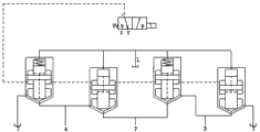
Fig. 2 is the principle schematic symbol diagram of high water base two-position four-way electro-hydraulic reversing valve.
Structural representation when Fig. 3 is high water base two-position four-way electro-hydraulic reversing valve pilot valve electromagnet energising.
Fig. 4 often opens cartridge valve modular construction figure.
Fig. 5 is normally closed cartridge valve modular construction figure.
Among the figure: the H. high voltage terminal is often opened the cartridge valve unit, the normally closed cartridge valve of I. low voltage terminal unit, and the J. low voltage terminal is often opened the cartridge valve unit, the normally closed cartridge valve of K. high voltage terminal unit, C. pilot valve water outlet; X. pilot valve water-supplying mouth, Y. pilot valve backwater mouth, 1. two-position three way guide Solenoid ball valve, 2. the two-position four-way valve main valve body 3. often leaves main through-flow chamber inlet; 4. often open main through-flow chamber outlet, 5. often open guide's control chamber, 6. often open the plug-in mounting valve pocket, 7. often open the plug-in mounting spool; 8. the plate sluicing chamber of often uncapping, the plate of 9. often uncapping, the plate end control chamber of 10. often uncapping, 11. normally open valve mouth end sluicing chambeies; The chamber enters the mouth 12. normally closed master is through-flow, and 13. normally closed masters are through-flow, and the chamber exports, 14. normally closed plug-in mounting valve pockets, 15. normally closed plug-in mounting spools; 16. the normal closed valve core Returnning spring, 17. normally closed cover plates, 18. normally closed cover plate sluicing chambeies, 19. normally closed cover plate end pressure chambeies; 20. valve-closed port end control chamber, 21. normally closed guide's control chambers, 22. pilot control opening, 23. Sealings.
Embodiment
Below in conjunction with accompanying drawing and mode of execution the utility model is further described.
As shown in Figure 1, the utility model comprises: two identical high voltage terminals of structure often open cartridge valve unit H and low voltage terminal is often opened cartridge valve unit J, two the normally closed cartridge valve of high voltage terminal unit K and the normally closed cartridge valve of low voltage terminal unit I that structure is identical; High voltage terminal is often opened and is connect water supply high pressure P mouth after often opening of cartridge valve unit H led the through-flow chamber of the normally closed master inlet connection of through-flow chamber inlet and the normally closed cartridge valve of high voltage terminal unit K; The outlet of the normally closed master of the normally closed cartridge valve of low voltage terminal unit I is through-flow chamber and low voltage terminal are often opened the main through-flow chamber of often opening of cartridge valve unit J and are exported and take back water low pressure T mouth; The normally closed master of the normally closed cartridge valve of low voltage terminal unit I is through-flow chamber inlet connects the first water outlet A mouth after often opening the main through-flow chamber outlet connection of often opening of cartridge valve unit H with high voltage terminal; Low voltage terminal is often opened and is connect the second water outlet B mouth after often opening of cartridge valve unit J led the through-flow chamber of the normally closed master outlet connection of through-flow chamber inlet and the normally closed cartridge valve of high voltage terminal unit K; Connect sluicing L mouth after two often uncap plate sluicing chamber and two normally closed cover plate sluicing chambeies connections; Often open for two and receive pilot control opening 22 after the normally closed guide's control chambers of guide's control chamber and two are communicated with.
Described high voltage terminal is often opened cartridge valve unit H and low voltage terminal, and often to open cartridge valve unit J structure identical; It often opens plug-in mounting spool 7 is thin ends and thick middle multidiameter shafts; With often open plug-in mounting valve pocket 6 and form three grades of concentric structures, form and often open main through-flow chamber inlet 3, often open main through-flow chamber outlet 4, often uncap plate end control chamber 10 and normally open valve mouth end sluicing chamber 11; Often open plug-in mounting spool 7, often open plug-in mounting valve pocket 6 and form with the two-position four-way valve main valve body 2 and the plate 9 assembling backs of often uncapping and often open guide's control chamber 5 and often uncap plate sluicing chamber 8; Often opening guide's control chamber 5 is communicated with the plate end control chamber 10 of often uncapping through the duct of often opening plug-in mounting valve pocket 6; Normally open valve mouth end sluicing chamber 11 is communicated with the plate sluicing chamber 8 of often uncapping through the duct of often opening plug-in mounting spool 7; Often open plug-in mounting spool 7 when often opening guide's control chamber 5 no pilot pressures, often open plug-in mounting spool 7 and open, often open main through-flow chamber inlet 3 and often open main through-flow chamber and export 4 and be communicated with; When often opening guide's control chamber 5 pilot pressure arranged, often open plug-in mounting spool 7 closures, often open main through-flow chamber inlet 3 and often open main through-flow chamber outlet 4 and isolate through the conical surface seal of often opening plug-in mounting spool valve port end.
The normally closed cartridge valve of described high voltage terminal unit K is identical with the normally closed cartridge valve of low voltage terminal unit I structure; Its normally closed plug-in mounting spool 15 is thin ends and thick middle multidiameter shafts; Form three grades of concentric structures with normally closed plug-in mounting valve pocket 14, form the through-flow chamber of normally closed master inlet 12, normally closed master is through-flow chamber outlet 13, normally closed cover plate end pressure chamber 19 and valve-closed port end control chamber 20; Normally closed plug-in mounting spool 15, normally closed plug-in mounting valve pocket 14 form normally closed guide's control chamber 21 and normally closed cover plate sluicing chambeies 18 with two-position four-way valve main valve body 2 and normally closed cover plate 17 assembling backs; Normally closed guide's control chamber 21 is communicated with valve-closed port end control chamber 20 through the duct of normally closed plug-in mounting valve pocket 14; Normally closed cover plate end pressure chamber 19 is communicated with the through-flow chamber of normally closed master inlet 12 through the duct of normally closed plug-in mounting spool 15; Normally closed plug-in mounting spool 15 when normally closed guide's control chamber 21 no pilot pressures, normally closed plug-in mounting spool 15 closures, normally closed master is through-flow, and chamber inlet 12 is isolated through the conical surface seal of normally closed plug-in mounting spool valve port end with normally closed master through-flow chamber outlet 13; When normally closed guide's control chamber 21 had pilot pressure, normally closed plug-in mounting spool 15 was opened, and normally closed master is through-flow, and chamber inlet 12 is communicated with normally closed master through-flow chamber outlet 13.
Shown in Fig. 2 schematic symbol diagram, the utility model is the plug-in type two-position four-way water hydraulic selector valve by 1 control of a two-position three way guide Solenoid ball valve.Guide's control chamber of four cartridge valve unit of two-position four-way valve main valve body 2 is connected with the pilot valve water outlet C of two-position three way guide Solenoid ball valve 1 through the duct of main valve body.When the pressure of pilot valve water-supplying mouth X was provided by the water supply high pressure P mouth of two-position four-way valve main valve body 2, whole valve was an internal control formula two-position four-way valve.When the pressure of pilot valve water-supplying mouth X was provided by external pilot pressure, then valve was the externally controlled type two-position four-way valve, need guarantee that pilot pressure is not less than the working pressure of main valve water supply high pressure P mouth when adopting the external control mode.
Be illustrated in figure 4 as the structural representation of often opening the cartridge valve unit; Often open plug-in mounting valve pocket 6, often open the plug-in mounting spool 7 and the plate 9 assembling back of often uncapping and form and often open main through-flow chamber inlet 3, often open main through-flow chamber outlet 4, normally open valve mouth end sluicing chamber 11, often uncap plate end control chamber 10 and Chang Kai guide's control chamber 5, often open guide's control chamber 5 and be communicated with the plate end control chamber 10 of often uncapping through the duct of often opening plug-in mounting valve pocket 6.When often opening guide's control chamber 5 no pilot pressures; The plate end control chamber 10 of then often uncapping does not have pressure yet; And often open main through-flow chamber inlet 3 pressure is arranged; Then hydraulic coupling acts on along through-flow direction and often opens on the plug-in mounting spool 7, and hydraulic resultant force makes often to be opened plug-in mounting spool 7 and open, and often opens main through-flow chamber inlet 3 and is communicated with Chang Kai master's through-flow chamber outlet 4; When often opening guide's control chamber 5 pilot pressure arranged; The plate end control chamber 10 of then often uncapping has pressure; Often open main through-flow chamber inlet 3 pressure is also arranged; But the annulus area of the plate end control chamber 10 of often uncapping is greater than the area of often opening main through-flow chamber inlet 3, and hydraulic resultant force makes often to be opened plug-in mounting spool 7 and close, and often opens main through-flow chamber inlet 3 and isolates with Chang Kai master's through-flow chamber outlet 4.
Be illustrated in figure 5 as the structural representation of normally closed cartridge valve unit; Chamber outlet 13 that normally closed plug-in mounting valve pocket 14, normally closed plug-in mounting spool 15 and normally closed cover plate 17 assembling backs form the through-flow chamber of normally closed masters inlet 12, normally closed master is through-flow, valve-closed port end control chamber 20, normally closed cover plate end pressure chamber 19 and normally closed guide's control chamber 21, normally closed guide's control chamber 21 is communicated with valve-closed port end control chamber 20 through the duct of normally closed plug-in mounting valve pocket 14.When normally closed guide's control chamber 21 no pilot pressures; Then valve-closed port end control chamber 20 does not have pressure yet; And the through-flow chamber of normally closed master inlet 12 has pressure, and the through-flow duct of normally closed cover plate end pressure chamber 19 through spool be communicated with the through-flow chamber of normally closed master inlet 12, but owing to the annulus area in normally closed cover plate end pressure chamber 19 greater than enter the mouth 12 area of the through-flow chamber of normally closed master; Then the cooperation of action of hydraulic force on spool firmly makes spool close, and normally closed master is through-flow, and chamber inlet 12 is isolated with normally closed master through-flow chamber outlet 13; When normally closed guide's control chamber 21 has pilot pressure; Then valve-closed port end control chamber 20 has pressure; Because of the area sum of the through-flow chamber of valve-closed port end control chamber 20 annulus areas and normally closed master inlet 12 annulus area greater than normally closed cover plate end pressure chamber 19; Then hydraulic pressure makes a concerted effort to make normally closed plug-in mounting spool 15 to open, and normally closed master is through-flow, and chamber inlet 12 is communicated with normally closed master through-flow chamber outlet 13.
Can know when guide's control chamber does not have pilot pressure by Fig. 4 and Fig. 5 that then often open the plug-in mounting spool and open, normally closed plug-in mounting spool is closed; When guide's control chamber had pilot pressure, it was closed often to open the plug-in mounting spool, and normally closed plug-in mounting spool is opened.
As shown in Figure 1; When the electromagnet of two-position three way guide Solenoid ball valve 1 is not switched on; Two-position three way guide Solenoid ball valve is in position, a left side, and then the water outlet of pilot valve connects pilot valve backwater mouth Y, and guide's control chamber of four cartridge valve unit does not have pilot pressure; Then the high voltage terminal spool of often opening cartridge valve unit H is opened, and the water supply high pressure P mouth of main valve body is communicated with the first water outlet A mouth; The spool of the normally closed cartridge valve of low voltage terminal unit I is closed, and first water outlet A mouth of main valve body and backwater low pressure T mouth are isolated; The spool of the normally closed cartridge valve of high voltage terminal unit K is closed, and the water supply high pressure P mouth of main valve body and the second water outlet B mouth are isolated; Low voltage terminal is often opened the spool of cartridge valve unit J and is opened, and the second water outlet B mouth of main valve body is communicated with backwater low pressure T mouth.Promptly when two-position three way guide Solenoid ball valve was not switched on, water supply high pressure P mouth was communicated with the first water outlet A mouth, and the second water outlet B mouth is communicated with backwater low pressure T mouth.
As shown in Figure 3; After the electromagnet energising of two-position three way guide Solenoid ball valve 1; Two-position three way guide Solenoid ball valve is in right position, and then the water outlet of pilot valve connects pilot valve water-supplying mouth X, and guide's control chamber of four cartridge valve unit has pilot pressure; Then high voltage terminal is often opened the spool closure of cartridge valve unit H, and the water supply high pressure P mouth of main valve body and the first water outlet A mouth are isolated; The spool of the normally closed cartridge valve of low voltage terminal unit I is opened, and the first water outlet A mouth of main valve body is communicated with backwater low pressure T mouth; The spool of the normally closed cartridge valve of high voltage terminal unit K is opened, and the water supply high pressure P mouth of main valve body is communicated with the second water outlet B mouth; The spool that low voltage terminal is often opened cartridge valve unit J is closed, and second water outlet B mouth of main valve body and backwater low pressure T mouth are isolated.Promptly after the energising of two-position three way guide Solenoid ball valve, water supply high pressure P mouth is communicated with the second water outlet B mouth, and the first water outlet A mouth is communicated with backwater low pressure T mouth.
In addition; The water of valve internal leakage through the hole link on cover plate duct and the main valve body together; And be connected to sluicing L mouth, if sluicing L mouth is the internal drainage type selector valve when being communicated with main valve backwater low pressure T mouth, be the formula selector valve that leaks when directly drawing independent draining as if sluicing L mouth.
Motive sealing that the cartridge valve unit of the utility model is inner and the static seal between plug-in mounting valve pocket and the main valve body use Sealing 23 to realize sealing respectively.In normally closed cartridge valve sluicing chamber design normal closed valve core Returnning spring 16 is housed and all is in open mode to prevent two-position four-way valve all spools before work; So that the situation that occurs the off-load cisco unity malfunction during main valve voltage supply, Returnning spring can guarantee that normally closed plug-in mounting spool can reset and close when no pressure is worked.The utility model can change the open and shut characteristic of spool as required through the diameter dimension ratio of regulating spool multidiameter shaft, spool through-flow damper with the buffering structure effect under, can control slow down spool movement velocity to alleviate the impact force of spool opening-closing process.Adopt the principle of the utility model, can go out the two-position four-way water hydraulic selector valve of multiple latus rectum according to the latus rectum size design that device requirement changes spool.
The utility model belongs to hydraulic pressure reversing control valve class, and it is big to have through-current capability, and good seal performance is highly sensitive, and contamination resistance is strong, and compact structure can be realized steadily the characteristics of switching-over at a high speed.Be particularly suitable for big flow with the hydraulic system that seawater, fresh water and high water base low-viscosity (mobile) liquid are driving medium, also can be used for mineral oil is the hydraulic system of medium.
Claims (3)
1. one kind high water base two-position four-way electro-hydraulic reversing valve; It is characterized in that comprising: two identical high voltage terminals of structure often open cartridge valve unit (H) and low voltage terminal is often opened cartridge valve unit (J), two the normally closed cartridge valve of high voltage terminal unit (K) and the normally closed cartridge valve of low voltage terminal unit (I) that structure is identical; High voltage terminal is often opened and is connect water supply high pressure P mouth after often opening of cartridge valve unit (H) led the through-flow chamber of the normally closed master inlet connection of through-flow chamber inlet and the normally closed cartridge valve of high voltage terminal unit (K); The outlet of the normally closed master of the normally closed cartridge valve of low voltage terminal unit (I) is through-flow chamber and low voltage terminal are often opened the main through-flow chamber of often opening of cartridge valve unit (J) and are exported and take back water low pressure T mouth; The normally closed master of the normally closed cartridge valve of low voltage terminal unit (I) is through-flow chamber inlet connects the first water outlet A mouth after often opening the main through-flow chamber outlet connection of often opening of cartridge valve unit (H) with high voltage terminal; Low voltage terminal is often opened and is connect the second water outlet B mouth after often opening of cartridge valve unit (J) led the through-flow chamber of the normally closed master outlet connection of through-flow chamber inlet and the normally closed cartridge valve of high voltage terminal unit (K); Connect sluicing L mouth after two often uncap plate sluicing chamber and two normally closed cover plate sluicing chambeies connections; Often open for two and receive pilot control opening (22) after the normally closed guide's control chambers of guide's control chamber and two are communicated with.
2. a kind of high water base two-position four-way electro-hydraulic reversing valve according to claim 1; It is characterized in that: described high voltage terminal is often opened cartridge valve unit (H) and low voltage terminal, and often to open cartridge valve unit (J) structure identical; It often opens plug-in mounting spool (7) is a thin ends and thick middle multidiameter shaft; With often open plug-in mounting valve pocket (6) and form three grades of concentric structures, form and often open main through-flow chamber inlet (3), often open main through-flow chamber outlet (4), often uncap plate end control chamber (10) and normally open valve mouth end sluicing chamber (11); Often open plug-in mounting spool (7), often open plug-in mounting valve pocket (6) and two-position four-way valve main valve body (2) and often open guide's control chamber (5) and the plate sluicing chamber (8) of often uncapping with the plate (9) of often uncapping assembling back formation; Often opening guide's control chamber (5) is communicated with the plate end control chamber (10) of often uncapping through the duct of often opening plug-in mounting valve pocket (6); Normally open valve mouth end sluicing chamber (11) is communicated with the plate sluicing chamber (8) of often uncapping through the duct of often opening plug-in mounting spool (7); Often open plug-in mounting spool (7) when often opening the no pilot pressure of guide's control chamber (5), often open plug-in mounting spool (7) and open, often open main through-flow chamber inlet (3) and often open main through-flow chamber and export (4) and be communicated with; Often opening guide's control chamber (5) when pilot pressure is arranged, often opening plug-in mounting spool (7) closure, often opening the through-flow chamber inlet of master (3) and often open main through-flow chamber outlet (4) through often opening the conical surface seal isolation of plug-in mounting spool valve port end.
3. a kind of high water base two-position four-way electro-hydraulic reversing valve according to claim 1; It is characterized in that: the normally closed cartridge valve of described high voltage terminal unit (K) is identical with the normally closed cartridge valve of low voltage terminal unit (I) structure; Its normally closed plug-in mounting spool (15) is a thin ends and thick middle multidiameter shaft; Form three grades of concentric structures with normally closed plug-in mounting valve pocket (14), form the through-flow chamber inlet of normally closed master (12), normally closed master is through-flow chamber outlet (13), normally closed cover plate end pressure chamber (19) and valve-closed port end control chamber (20); Normally closed plug-in mounting spool (15), normally closed plug-in mounting valve pocket (14) form normally closed guide's control chamber (21) and normally closed cover plate sluicing chamber (18) with two-position four-way valve main valve body (2) and normally closed cover plate (17) assembling back; Normally closed guide's control chamber (21) is communicated with valve-closed port end control chamber (20) through the duct of normally closed plug-in mounting valve pocket (14); Normally closed cover plate end pressure chamber (19) is communicated with the through-flow chamber inlet of normally closed master (12) through the duct of normally closed plug-in mounting spool (15); Normally closed plug-in mounting spool (15) is when the no pilot pressure of normally closed guide's control chamber (21); Normally closed plug-in mounting spool (15) closure, normally closed master is through-flow, and chamber inlet (12) is isolated through the conical surface seal of normally closed plug-in mounting spool valve port end with the through-flow chamber outlet of normally closed master (13); When pilot pressure was arranged, normally closed plug-in mounting spool (15) was opened at normally closed guide's control chamber (21), and normally closed master is through-flow, and chamber inlet (12) is communicated with the through-flow chamber outlet of normally closed master (13).
Priority Applications (1)
| Application Number | Priority Date | Filing Date | Title |
|---|---|---|---|
| CN2011204252183U CN202301255U (en) | 2011-11-01 | 2011-11-01 | High-water-base two-position four-way electro-hydraulic reversing valve |
Applications Claiming Priority (1)
| Application Number | Priority Date | Filing Date | Title |
|---|---|---|---|
| CN2011204252183U CN202301255U (en) | 2011-11-01 | 2011-11-01 | High-water-base two-position four-way electro-hydraulic reversing valve |
Publications (1)
| Publication Number | Publication Date |
|---|---|
| CN202301255U true CN202301255U (en) | 2012-07-04 |
Family
ID=46370164
Family Applications (1)
| Application Number | Title | Priority Date | Filing Date |
|---|---|---|---|
| CN2011204252183U Expired - Lifetime CN202301255U (en) | 2011-11-01 | 2011-11-01 | High-water-base two-position four-way electro-hydraulic reversing valve |
Country Status (1)
| Country | Link |
|---|---|
| CN (1) | CN202301255U (en) |
Cited By (3)
| Publication number | Priority date | Publication date | Assignee | Title |
|---|---|---|---|---|
| CN102364123A (en) * | 2011-11-01 | 2012-02-29 | 浙江大学 | Cartridge type two-position four-way water hydraulic reversing valve |
| CN108005984A (en) * | 2017-12-01 | 2018-05-08 | 宁波文泽机电技术开发有限公司 | A kind of guide type electromagnetic ball valve |
| CN109538567A (en) * | 2019-01-04 | 2019-03-29 | 天津华宁电子有限公司 | A kind of insert type change-over valve core |
-
2011
- 2011-11-01 CN CN2011204252183U patent/CN202301255U/en not_active Expired - Lifetime
Cited By (5)
| Publication number | Priority date | Publication date | Assignee | Title |
|---|---|---|---|---|
| CN102364123A (en) * | 2011-11-01 | 2012-02-29 | 浙江大学 | Cartridge type two-position four-way water hydraulic reversing valve |
| CN102364123B (en) * | 2011-11-01 | 2014-06-11 | 浙江大学 | Cartridge type two-position four-way water hydraulic reversing valve |
| CN108005984A (en) * | 2017-12-01 | 2018-05-08 | 宁波文泽机电技术开发有限公司 | A kind of guide type electromagnetic ball valve |
| CN109538567A (en) * | 2019-01-04 | 2019-03-29 | 天津华宁电子有限公司 | A kind of insert type change-over valve core |
| CN109538567B (en) * | 2019-01-04 | 2024-04-05 | 天津华宁电子有限公司 | Plug-in type reversing valve core |
Similar Documents
| Publication | Publication Date | Title |
|---|---|---|
| CN202091555U (en) | Slide-valve-type two-position and three-way reversing valve | |
| CN203548393U (en) | Auxiliary hydraulic system and concrete pumping equipment | |
| CN102364123B (en) | Cartridge type two-position four-way water hydraulic reversing valve | |
| CN202301255U (en) | High-water-base two-position four-way electro-hydraulic reversing valve | |
| CN201891689U (en) | Cartridge inserted two-position three-way electro-hydraulic reversing valve | |
| CN103104569B (en) | Three-position four-way water pressure magnetic exchange valve used in deep sea | |
| CN201037377Y (en) | Horizontal positioning drilling machine valve control interflow speeding up hydraulic system | |
| CN103062444B (en) | Water pressure plug-in type three-position four-way electromagnetic directional valve | |
| CN112983909A (en) | Movable arm hydraulic system | |
| CN101456607B (en) | Water pressure driven switching valve group | |
| CN102734268A (en) | Engineering machinery, method for preheating oil drainage path of hydraulic motor and hydraulic system | |
| CN201836004U (en) | Hydraulic system | |
| CN108150643A (en) | A kind of shift valve block, power head multi gear level controlling system and control method and rotary drilling rig | |
| CN104033438A (en) | Multi-functional hydraulic-jamming preventing pilot valve for electro-hydraulic directional valve | |
| CN201173298Y (en) | Straight moving type double-way electromagnetic valve | |
| CN201502577U (en) | Hydraulic reversing device | |
| CN107387473B (en) | Tandem channel-borrowing type multipath hydraulic control device | |
| CN201288715Y (en) | Directional control valve driven by hydraulic pressure | |
| CN201173311Y (en) | Direct moving type two position three-way solenoid valve | |
| CN106735394A (en) | A kind of dual sided porous drilling hydraulic system of modular machine tool | |
| CN207935420U (en) | A kind of shift valve block, the more shift control systems of power head and rotary drilling rig | |
| CN102619801A (en) | Pure-water bidirectional opposed piezoelectric ceramic reversing valve | |
| CN203189375U (en) | Four-motor rotary multistage speed regulating valve | |
| CN202100551U (en) | Multi-way reversing valve | |
| CN103148044B (en) | Three-motor rotary multi-stage speed regulating valve |
Legal Events
| Date | Code | Title | Description |
|---|---|---|---|
| C14 | Grant of patent or utility model | ||
| GR01 | Patent grant | ||
| AV01 | Patent right actively abandoned |
Granted publication date: 20120704 Effective date of abandoning: 20140611 |
|
| RGAV | Abandon patent right to avoid regrant |