A kind of rack of solar water heater structure
Technical field
The utility model relates to the solar water heater erecting device, especially a kind of vacuum tube collector formula rack of solar water heater structure.
Background technology
At present, known rack of solar water heater is made up of parts such as barrel, foreleg, back leg, tail box, stull, long cross-bridging, diagonal brace and lower margins.Number according to vacuum tube collector is different, and the corresponding support that produces different pipe numbers is divided into two on chip and three series on chip again; But wherein rack of solar water heater stull, diagonal brace design of part confusion, in two vacuum tube collector supports on chip, back cross-bridging length is all longer than foreleg; The vacuum tube collector support packing case size disunity that causes different numbers; Transport inconvenience, also cause waste, and flat-top can not be general with the installation of oblique top in installation process; The scope of application of support is reduced greatly, have limitation.
Summary of the invention
In order to overcome the deficiency of prior art, the utility model provides a kind of and puts down, pitched roof is general, and packed and transported is the rack of solar water heater structure easily.
The utility model solves the technical scheme that its technical problem adopted: a kind of rack of solar water heater structure; Comprise foreleg, back leg, barrel, tail box, stull, diagonal brace and tail box; Said barrel is dismountable to be located on the back leg; One end of said foreleg is fixedly connected with barrel, and said tail box is located at the other end of foreleg, and the two ends of said stull are fixedly connected with two barrels respectively or two back legs are fixedly connected or the fixed connection of two forelegs; One end of said diagonal brace is fixedly connected with stull, and the other end of diagonal brace is fixedly connected with foreleg or barrel is fixedly connected; It is characterized in that also comprising four short cross-bridgings and contiguous block; One end of said four short cross-bridgings is connected together with contiguous block respectively and forms X type chi structure, and the other end of four short cross-bridgings is fixedly connected with two forelegs respectively or two barrels and back leg fixed connection.
Supported underneath end at said foreleg and back leg is respectively equipped with lower margin.
Between said stull and barrel, be fixed with long cross-bridging, stull, barrel and the long cross-bridging three formation triangular structure that interconnects.
On said contiguous block, be provided with the connecting hole at five places, be connected with contiguous block through screw, plain cushion, nut and connecting hole after the end mutual superposition of said four short cross-bridgings.
The utility model beneficial effect compared with prior art is: realize support installation versatility, order is originally simple in structure, installation workload is little, has reached the uniformity and the standardization of different vacuum tube number supports packings.
Description of drawings
Fig. 1 is the two flat roof structure sketch mapes on chip of the utility model;
Fig. 2 is the exploded view of short cross-bridging and contiguous block;
Fig. 3 is the two pitched roof structural representations on chip of the utility model;
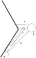
Fig. 4 is the pitched roof side scheme of installation of the utility model;
Fig. 5 is the three flat roof structure sketch mapes on chip of the utility model;
Fig. 6 is the three pitched roof structural representations on chip of the utility model.
The specific embodiment
Below in conjunction with accompanying drawing and embodiment utility model is specifically further specified.
Arrive shown in Figure 6 like Fig. 1; It is a kind of rack of solar water heater structure; Comprise foreleg 1, back leg 2, barrel 3, tail box 4, stull 5, diagonal brace 6 and tail box 4, said barrel 3 dismountable being located on the back leg 2, an end of said foreleg 1 is fixedly connected with barrel 3; The other end and this end that said tail box 4 is located at foreleg 1 are supported on the roof; The two ends of said stull 5 are fixedly connected with two barrels 3 respectively or two back legs are fixedly connected or 1 fixed connection of two forelegs, and an end of said diagonal brace 6 is fixedly connected with stull 5, and the other end of diagonal brace 6 is fixedly connected with foreleg 1 or barrel 3 is fixedly connected; The utility model characteristics are also to comprise four short cross-bridgings 7 and contiguous block 8; One end of said four short cross-bridgings 7 is connected together with contiguous block 8 respectively and forms X type chi structure, and the other end of four short cross-bridgings 7 is fixedly connected with two forelegs 1 respectively or two barrels 3 and back leg 2 fixed connections.Supported underneath end at said foreleg 1 and back leg 2 is respectively equipped with lower margin 9.During installation; Four short cross-bridgings 7 and contiguous block 8 form X type chi structures; This X type chi structure improves the rack of solar water heater bulk strength with stull 5; Simultaneously can confirm the utility model support manner of packing, reach the uniformity and the standardization of different vacuum tube number support packings according to foreleg 1 length.
Between said stull 5 and barrel 3, be fixed with long cross-bridging 15, stull 5, barrel 3 and the long cross-bridging 15 threes formation triangular structure that interconnects.
On said contiguous block 8, be provided with the connecting hole 81 at five places, be connected with contiguous block 8 through screw 10, plain cushion 11, nut 12 and connecting hole 81 after the end mutual superposition of said four short cross-bridgings 7, further promote the intensity of rack of solar water heater.
Shown in 1 figure, when installing, contiguous block 8 and four short cross-bridgings 7 are installed between two barrels 3 and two back legs 2 in the flat-top room; The two ends of a stull 5 are fixedly connected with two barrels 3 respectively, the two ends of another root stull 5 are separately fixed between two forelegs 1, an end of two diagonal braces 6 respectively with foreleg 1 on stull 5 fixing; The other end of two diagonal braces 6 is fixing like Fig. 3, shown in 4 with two forelegs 1 respectively, when pitched roof 13 is installed, and removal back leg 2; Contiguous block 8 and four short cross-bridgings 7 are installed between two forelegs 1; Two stulls 5 are installed between two barrel 3 rear portions, and two diagonal braces 6 are installed in upper and lower two stulls 5, and solar water heater water tank 14 is installed on barrel 3 tops; Vacuum tube collector 13 openings one end is connected in the water tank 14, and the other end is connected in the tail box 4.
As shown in Figure 5, when its be three supporting structures on chip also, and when being mounted on the flat-top room; The two ends of two long cross-bridgings 15 interconnect with barrel 3, stull 5 threes respectively; Constitute triangular structure, make rack of solar water heater intensity improve stable performance.
As shown in Figure 6, when pitched roof is installed, removal back leg 2, two long cross-bridging 15 traversing carriages are anterior, and two long cross-bridging one endlaps are added on together, are connected with middle foreleg 1 with stull 5, and the other end links to each other with left and right limit foreleg 1 respectively.The support rear portion is connected together through stull 5 and three barrels, for further strengthening integral support intensity, between two stulls 5 in rear portion, increases by four diagonal braces 6.