CN202230130U - Multi-loop current type detection module - Google Patents
Multi-loop current type detection module Download PDFInfo
- Publication number
- CN202230130U CN202230130U CN2011203473259U CN201120347325U CN202230130U CN 202230130 U CN202230130 U CN 202230130U CN 2011203473259 U CN2011203473259 U CN 2011203473259U CN 201120347325 U CN201120347325 U CN 201120347325U CN 202230130 U CN202230130 U CN 202230130U
- Authority
- CN
- China
- Prior art keywords
- circuit
- detection module
- signal
- chip microcomputer
- mode detection
- Prior art date
- Legal status (The legal status is an assumption and is not a legal conclusion. Google has not performed a legal analysis and makes no representation as to the accuracy of the status listed.)
- Expired - Fee Related
Links
Images

Abstract
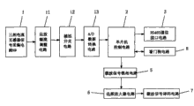
The utility model relates to a multi-loop current type detection module, comprising a three-phase current transformer signal acquisition circuit and a one-chip microcomputer control circuit, wherein the output signals of the multi-loop three-phase current transformer signal acquisition circuit are transmitted to the one-chip microcomputer control circuit sequentially via an operation amplifier rectification adjusting circuit, a simulation switch circuit, and an A/D data converting circuit; the signals are transmitted to an RS485 communication interface circuit and a carrier wave signal phase lock circuit via the control of the one-chip microcomputer control circuit; and the output signals of the carrier wave signal phase lock circuit are sent to a carrier wave signal decoding circuit via a frequency selective amplifier circuit. The multi-loop current type detection module model adopts multi-loop cycle detection. After the judgment of a one-chip microcomputer, the multi-loop current type detection module emits alarming signals to a host via carrier wave signals or RS485 bus, thereby timely and effectively carrying out alarming at the earliest time.
Description
Technical field
The utility model relates to a kind of detection module, particularly be a kind of multiloop current mode detection module.
Background technology
The electrical fire major part is worn out by the long-time use of circuit or excess current causes, but traditional isolating switch product can only be gathered three-phase current signal separately, can not satisfy the many practical challenges in distribution system loop.
The utility model content
The purpose of the utility model is to overcome above-mentioned deficiency, and a kind of multiloop current mode detection module is provided.
The utility model solves the technical scheme that its technical matters adopted: a kind of multiloop current mode detection module; Comprise threephase current transformer signal acquisition circuit and single chip machine controlling circuit; The output signal of the threephase current transformer signal acquisition circuit of multichannel transfers to single chip machine controlling circuit through amplifier rectification adjustment circuit, analog switching circuit, A/D data converting circuit successively; Export RS485 communication interface circuit, carrier signal phase lock circuitry to by single chip machine controlling circuit control, the output signal of said carrier signal phase lock circuitry sends to the carrier signal decoding scheme through the frequency-selecting amplifier circuit.
Said single chip machine controlling circuit and watchdog circuit bidirectional data transfers.
Said threephase current transformer signal acquisition circuit is gathered current signal through the amorphous ZCT.
Said amplifier rectification adjustment circuit is mainly by half-wave rectifying circuit, and current limliting bleeder circuit, filter integral circuit constitute.
Said RS485 communication interface circuit transmits warning message through system bus to the fire protection control center PC through SN75176 signal transmitting and receiving chip.
Through adopting above-mentioned technical scheme, the beneficial effect of the utility model is: the utility model adopts the multiloop cycle detection, after the comprehensive judgement of single-chip microcomputer, sends alerting signal through carrier signal or RS485 bus to main frame, and the timely and effective very first time reports to the police.
Description of drawings
Fig. 1 is the frame assumption diagram of the utility model;
Fig. 2 is the circuit theory diagrams of the utility model.
Embodiment
As shown in Figure 1; The multiloop current mode detection module of the utility model; Comprise threephase current transformer signal acquisition circuit 1 and single chip machine controlling circuit 2; The output signal of the threephase current transformer signal acquisition circuit 1 of multichannel transfers to single chip machine controlling circuit 2 through amplifier rectification adjustment circuit 11, analog switching circuit 12, A/D data converting circuit 13 successively; Export RS485 communication interface circuit 3, carrier signal phase lock circuitry 5 to by single chip machine controlling circuit 2 controls, the output signal of said carrier signal phase lock circuitry 5 sends to carrier signal decoding scheme 7 through frequency-selecting amplifier circuit 6, said single chip machine controlling circuit 2 and watchdog circuit 8 bidirectional data transfers.
This module adopts the amorphous current transformer to gather current signal, when phase line is passed current transformer, gathers current signal; The electric current that is passed through is big more, and the alternating voltage of induction is big more thereupon, and this voltage signal is after the rectification adjustment; Be sent to analog switch, carry out the shunt cycle detection, handle through the single-chip microcomputer logical data; Show current current value in real time; When a certain phase line surpasses the setting current value, send the sound and light alarm signal, export fire protection control center to through RS485 system bus signal or carrier signal.
As shown in Figure 2; When the L1 phase current mutual inductor is sensed ac voltage signal when excessive, the secondary of current transformer L1 can produce voltage signal, and this signal is the half-wave rectifying circuit through being made up of resistance R 1, capacitor C 7, capacitor C 8, capacitor C 9, diode D7 earlier; Again through resistance R 2 current limlitings; Resistance R 1 dividing potential drop, diode D7 rectification is to capacitor C 8 chargings; Filter integral circuit output linear voltage through being made up of resistance R 14, capacitor C 10, capacitor C 11 is imported analog switch chip U5 the 13rd pin after diode ZW1 pressure limiting at last.This moment, the 13rd pin of analog switch chip U5 was a high level; Its 3rd pin output terminal is output as high level; Input end the 2nd pin of input A/D conversion chip U4; After the inner A/D data-switching of A/D conversion chip U4; The 1st, 37,39 pin and A/D conversion chip U4 the 5th, 6,7 pin by single-chip microcomputer U1 are formed datel circuit; Through single-chip microcomputer U1 comprehensive judge detect signal after the U4 data-switching, surpass single-chip microcomputer U1 inner setting value, and when being judged as supply line's excess current; This moment, single-chip microcomputer U1 sent control signal, and communication interface the 1st, 2,3,4 pin of being exported the 1st pin, the 2nd pin, the 3rd pin and the SN75176 signal transmitting and receiving chip U7 that are connected respectively to control chip U2 by the 10th pin, the 11st pin, the 25th pin serial data of single-chip microcomputer U1 transmit warning message through system bus to the fire protection control center PC with L1 overcurrent signal mutually.
The multivibrator that another route LM567 tone decoder IC1 and peripheral electric capacity 2C1, resistance 2R1, resistance 2R2 thereof constitute is formed phase lock circuitry; Its oscillation frequency is by the parameter determining of electric capacity 2C1, resistance 2R1, and carrier frequency is adjusted in the 150-300KHZ scope.Elementary L1, electric capacity 1C2, capacitor 2C3 by triode Q1, audio-frequency transformer (AFT) T constitute the frequency-selecting amplifier circuit; The 4th pin output high level signal by single-chip microcomputer U1; Make LM567 tone decoder IC1 obtain working power; LM567 tone decoder IC1 starts working, and is coupled on local telephone network speaking wire or the AC network AC220V power lead and is sent by secondary L2, the electric capacity 2C4 of audio-frequency transformer (AFT) T, sends data-signal to the carrier wave main frame.Said carrier signal decoding scheme; Audio-frequency transformer (AFT) T1, LM567 ATD IC2, triode Q2, LED by connecting successively constitute; The time constant of resistance 4R1, capacitor C 5 networks has determined the voltage controlled oscillator of LM567 ATD IC2; When the carrier wave extension set when main frame sends 150-300KHZ carrier wave command signal; Be coupled to the secondary L3 of audio-frequency transformer (AFT) T through capacitor C 1, audio-frequency transformer (AFT) T1, its secondary L3, capacitor C 2, capacitor C 3 are formed a carrier wave frequency selection network.Signal after the frequency-selecting is coupled to the 3rd pin signal input part of LM567 ATD IC2 through capacitor C 4; After LM567 ATD IC2 decoding,, make triode Q2 conducting by its 8th pin output terminal output low level; LED is lighted; Received the carrier data signal of extension set, explained that electric fault has appearred in power supply commonly used, reaches real time and on line monitoring.
The current transformer principle of other phase is identical with the principle of L1 phase current mutual inductor, just no longer repeats here.
An above-described preferred embodiment that is merely the utility model can not limit the scope that this practicality is implemented, and every equalization of being done according to the utility model claim changes and decorates, and all should still belong to the scope that the utility model is contained.
Claims (5)
1. multiloop current mode detection module; It is characterized in that: comprise threephase current transformer signal acquisition circuit (1) and single chip machine controlling circuit (2); The output signal of the threephase current transformer signal acquisition circuit (1) of multichannel transfers to single chip machine controlling circuit (2) through amplifier rectification adjustment circuit (11), analog switching circuit (12), A/D data converting circuit (13) successively; Export RS485 communication interface circuit (3), carrier signal phase lock circuitry (5) to by single chip machine controlling circuit (2) control, the output signal of said carrier signal phase lock circuitry (5) sends to carrier signal decoding scheme (7) through frequency-selecting amplifier circuit (6).
2. multiloop current mode detection module according to claim 1 is characterized in that: said single chip machine controlling circuit (2) and watchdog circuit (8) bidirectional data transfers.
3. multiloop current mode detection module according to claim 1 is characterized in that: said threephase current transformer signal acquisition circuit (1) is gathered current signal through the amorphous ZCT.
4. multiloop current mode detection module according to claim 1 is characterized in that: said amplifier rectification adjustment circuit (11) is mainly by half-wave rectifying circuit, and current limliting bleeder circuit, filter integral circuit constitute.
5. multiloop current mode detection module according to claim 1 is characterized in that: said RS485 communication interface circuit (3) transmits warning message through system bus to the fire protection control center PC through SN75176 signal transmitting and receiving chip.
Priority Applications (1)
| Application Number | Priority Date | Filing Date | Title |
|---|---|---|---|
| CN2011203473259U CN202230130U (en) | 2011-09-16 | 2011-09-16 | Multi-loop current type detection module |
Applications Claiming Priority (1)
| Application Number | Priority Date | Filing Date | Title |
|---|---|---|---|
| CN2011203473259U CN202230130U (en) | 2011-09-16 | 2011-09-16 | Multi-loop current type detection module |
Publications (1)
| Publication Number | Publication Date |
|---|---|
| CN202230130U true CN202230130U (en) | 2012-05-23 |
Family
ID=46080714
Family Applications (1)
| Application Number | Title | Priority Date | Filing Date |
|---|---|---|---|
| CN2011203473259U Expired - Fee Related CN202230130U (en) | 2011-09-16 | 2011-09-16 | Multi-loop current type detection module |
Country Status (1)
| Country | Link |
|---|---|
| CN (1) | CN202230130U (en) |
Cited By (1)
| Publication number | Priority date | Publication date | Assignee | Title |
|---|---|---|---|---|
| CN102360038A (en) * | 2011-09-16 | 2012-02-22 | 福建俊豪电子有限公司 | Multi-loop current type detection module |
-
2011
- 2011-09-16 CN CN2011203473259U patent/CN202230130U/en not_active Expired - Fee Related
Cited By (1)
| Publication number | Priority date | Publication date | Assignee | Title |
|---|---|---|---|---|
| CN102360038A (en) * | 2011-09-16 | 2012-02-22 | 福建俊豪电子有限公司 | Multi-loop current type detection module |
Similar Documents
| Publication | Publication Date | Title |
|---|---|---|
| CN102393485A (en) | Detection module for multi-loop leakage current | |
| CN102394493A (en) | Electrical signal collection monitoring device | |
| CN202256482U (en) | Multi-loop leakage current detecting module | |
| CN202189134U (en) | Power failure monitoring device | |
| CN102156468B (en) | System for complementary power supply between small power station and commercial power grid | |
| CN202230130U (en) | Multi-loop current type detection module | |
| CN102360038A (en) | Multi-loop current type detection module | |
| CN204965088U (en) | Remote monitoring device for transformer | |
| CN201749354U (en) | 32-way switching value signal collector | |
| CN208737304U (en) | A kind of Distribution of Natural formula energy remote centralized control system | |
| CN202084918U (en) | Electric equipment monitoring system | |
| CN201975769U (en) | Low-voltage power-distribution neutral line monitoring device | |
| CN205484517U (en) | Grid voltage current monitoring system | |
| CN202230159U (en) | Fault monitoring device of electric equipment | |
| CN202230589U (en) | Electrical signal acquisition monitoring device | |
| CN204422013U (en) | A kind of system of water level monitoring | |
| CN201845048U (en) | Remote monitoring device for transformers | |
| CN202230572U (en) | Novel alarm module | |
| CN203243449U (en) | Image transmission and information acquisition remote control system based on 3G network | |
| CN202586856U (en) | Generator control device with wireless control | |
| CN201965719U (en) | Short circuit monitoring warning circuit of electrical equipment | |
| CN202172264U (en) | Zero line monitoring device | |
| CN205140192U (en) | Terminal of zooming out that power consumption information acquisition GPRS is wireless based on 10kV induction electricity -taking | |
| CN205809161U (en) | Electric measurement transducer | |
| CN202172255U (en) | Protective device for low-voltage power grid |
Legal Events
| Date | Code | Title | Description |
|---|---|---|---|
| C14 | Grant of patent or utility model | ||
| GR01 | Patent grant | ||
| C17 | Cessation of patent right | ||
| CF01 | Termination of patent right due to non-payment of annual fee |
Granted publication date: 20120523 Termination date: 20130916 |