CN202205978U - Automatic socket adopting modular power supply and sensor management for two domestic appliances - Google Patents
Automatic socket adopting modular power supply and sensor management for two domestic appliances Download PDFInfo
- Publication number
- CN202205978U CN202205978U CN2011202109335U CN201120210933U CN202205978U CN 202205978 U CN202205978 U CN 202205978U CN 2011202109335 U CN2011202109335 U CN 2011202109335U CN 201120210933 U CN201120210933 U CN 201120210933U CN 202205978 U CN202205978 U CN 202205978U
- Authority
- CN
- China
- Prior art keywords
- sensor
- relay
- solid relay
- drive circuit
- triode
- Prior art date
- Legal status (The legal status is an assumption and is not a legal conclusion. Google has not performed a legal analysis and makes no representation as to the accuracy of the status listed.)
- Expired - Fee Related
Links
Images
Abstract
An automatic socket adopting a modular power supply and sensor management for two domestic appliances belongs to a connector for a sensor and a domestic appliance, is based on an automatic socket adopting sensor management for two domestic appliances, and adopts the modular power supply to replace a DC stabilized voltage power supply to work as a working power supply; and two sensors respectively control a single domestic appliance (socket), and together manage two groups of single pole double throw switches based on a relationship of logical OR. The utility model is applied to a switching value output, level output or pulse output sensor for jointly controlling the automatic operation of multiple domestic appliances and various electric appliances, and has a light weight and a small volume.
Description
Technical field
The utility model belongs to the application electric technology field, particularly relates to a kind of interface arrangement that uses transducer to realize household electrical appliance and electronic installation automatic operating.
Background technology
Utility application " the two-way household electrical appliance automation socket of powered battery, sensor management " and " the two-way household electrical appliance automation socket of sensor management " of submitting Patent Office of State Intellectual Property Office examination the same period to respectively with battery and D.C. regulated power supply as working power; Use two transducers to manage No. one household electrical appliance separately; And control electronic switch again with the relation of logic OR, be applicable to the automation or the guard against theft and alarm system of multichannel household electrical appliance and electronic installation.
Summary of the invention
The purpose of the utility model is to provide the two-way household electrical appliance automation socket of a kind of modular power source power supply, sensor management; It adopts modular power source as working power; Use two transducers and manage the operation of No. one household electrical appliance respectively; And with the common action of controlling two groups of single-pole double-throw switch (SPDT)s of the relation of logic OR, said transducer can be Switch-Output Type, the level output type or pulse output type.
The utility model solves the technical scheme that its technical problem adopted:
Be the basis with " the two-way household electrical appliance automation socket of sensor management "; Replace D.C. regulated power supply with modular power source; Two ac input ends of said modular power source are connected respectively to the phase line (L line) and the working zero line (N line) of civil power, and its two outputs are respectively as the positive pole and the negative pole of the working power of the utility model.
The utility model cooperates two transducers to use; The incident of being concerned about separately with sensor monitors; Two output-controlled ends of the corresponding ac solid relay of output signal triggering that they sense events produced are driven conducting; Corresponding socket electrifying electricity, it gets electric time length and can regulate.Each road transducer moves, and all can cause the direct current electromagnetic relay action in the device.
Compare with utility application " the two-way household electrical appliance automation socket of powered battery, sensor management " and " the two-way household electrical appliance automation socket of sensor management "; The utility model adopts modular power source to replace battery pack or D.C. regulated power supply provides working power; Its strong point is: the trouble of not only having avoided changing battery; Make and to replace analog electronic switching circuit by relay, be applicable to various electronic installations, also saved non-ferrous metal; Alleviate weight widely, reduced volume.
Description of drawings
Below in conjunction with accompanying drawing, further specify the utility model.
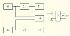
Fig. 1 is the composition block diagram of the utility model.
Fig. 2 is the schematic diagram of one road sensor control circuit; Wherein, Switch S+, S-represents the pair of sensors terminals respectively; Sensor terminals S+ is applicable to that output variable is rising edge saltus step type or closed type transducer, and sensor terminals S-is applicable to that output variable is trailing edge saltus step type or open type transducer.
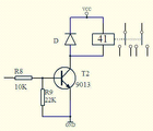
Fig. 3 is the schematic diagram of direct current electromagnetic relay and drive circuit thereof.
Among Fig. 1,11., 12. sensor interface circuitries, 21., 22. ac solid relay and drive circuits thereof, 31., 32. ac solid relay output circuits, 4. direct current electromagnetic relay and drive circuit thereof, 5. modular power source.
Among Fig. 2,1. monostable flipflop CD4098,2. ac solid relay, 3. socket.
Among Fig. 3,41. direct current electromagnetic relays.
Embodiment
As shown in Figure 1, the utility model comprises: two-way sensor control circuit, direct current electromagnetic relay and drive circuit thereof (4), supply main and plug thereof and a modular power source (5) cooperate two transducers to use.Among Fig. 1, road sensor control circuit above sensor interface circuitry (11), ac solid relay and drive circuit (21) thereof, ac solid relay output circuit (31) have been formed; Road sensor control circuit below sensor interface circuitry (12), ac solid relay and drive circuit (22) thereof, ac solid relay output circuit (32) have been formed.The structure of this two-way sensor control circuit is identical; Fig. 2 represented wherein a road; Wherein, monostable flipflop (1), sensor terminals S+ and sensor terminals S-, isolation resistance R5, isolating diode D1 and hand switch K have formed sensor interface circuitry (11) or sensor interface circuitry (12).Monostable flipflop (1) can be made up of CD4098 and peripheral circuit thereof; Its rising edge triggers input, trailing edge triggers input and connects a pull down resistor respectively; Also be connected respectively to the end of sensor terminals S+ and sensor terminals S-, the other end of sensor terminals S+ and sensor terminals S-is connected to the positive pole of working power; The output Q of monostable flipflop (1) is connected respectively to hand switch K and ac solid relay and drive circuit (21) or ac solid relay and drive circuit (22) thereof through isolation resistance R5, also is connected to direct current electromagnetic relay and drive circuit (4) thereof through an isolating diode D1; The other end of hand switch K is received the positive pole of working power.The electronic switch that ac solid relay and drive circuit thereof adopt a triode T1 to constitute drives the input of ac solid relay (2).Each road ac solid relay and drive circuit thereof all comprise a base resistance R3, base stage pull down resistor R4, triode T1, LED and an ac solid relay (2); The end of base resistance R3 is as the signal input part of this road ac solid relay and drive circuit (21) or ac solid relay and drive circuit (22) thereof; Its other end and base stage pull down resistor R4 are connected to the base stage of triode T1, and two inputs of LED, ac solid relay (2), the collector electrode of triode T1 and emitter thereof and working power are formed series loop.Ac solid relay output circuit (31) or ac solid relay output circuit (32) comprising: two controlled outputs of ac solid relay (2), fuse FU, piezo-resistance MOV and a three-phase socket (3); Wherein, Piezo-resistance MOV is connected in parallel on two controlled outputs of ac solid relay (2); A controlled output of ac solid relay (2) is connected in series to the phase line (L line) of civil power through fuse FU; Another controlled output of ac solid relay (2) is connected to an electrode of three-phase socket (3), and the non-protective earthing electrode of another of three-phase socket (3) is connected to the working zero line (N line) of civil power.The circuit of foregoing circuit and utility model application " the two-way household electrical appliance automation socket of powered battery, sensor management " and utility model application " the two-way household electrical appliance automation socket of sensor management " is basic identical.The difference of the application and it two is: the application's working power is not to adopt dry cell or D.C. regulated power supply; But supply with by modular power source (5); Two ac input ends of modular power source (5) are connected respectively to the phase line (L line) and the working zero line (N line) of civil power, and its two outputs are respectively as the positive pole and the negative pole of the working power of the utility model.
The circuit of direct current electromagnetic relay and drive circuit thereof (4) is as shown in Figure 3; The electronic switch that adopts triode to constitute drives direct current electromagnetic relay (41), comprising: a base resistance R8, a base stage pull down resistor R9, triode T2, a direct current electromagnetic relay (41) and a protection diode D.The end of base resistance R8 is as the signal input part of this direct current electromagnetic relay and drive circuit (4) thereof, and its other end and base stage pull down resistor R9 are connected to the base stage of triode T2.The negative pole series connection of the coil of the positive pole of working power, direct current electromagnetic relay (41), the collector electrode of triode T2 and emitter and working power; The negative pole of protection diode D connects the positive pole of working power, and the positive pole of diode D connects the collector electrode of triode T2.
Modular power source (5) is selected the AC-DC transformation model for use, and it is output as single channel, and output voltage is 3V-18V, and output current is as far as possible little, looks the supply of electric power situation, selects for use the imported or narrow pressure of wide pressure imported.
Similar " the home electronic appliance automation socket of powered battery, sensor management "; As shown in Figure 2; Marquis when not using transducer; Closed hand switch K can make two output-controlled ends of ac solid relay SSR (2) be in conducting state, and at this moment, the utility model is equal to the common power socket.
Claims (1)
1. the two-way household electrical appliance automation socket of modular power source power supply, sensor management, it is characterized in that: it is made up of two-way sensor control circuit, direct current electromagnetic relay and drive circuit thereof, supply main and plug thereof and a modular power source; Wherein, two ac input ends of modular power source are connected respectively to the phase line and the working zero line of civil power, and its two outputs are respectively as the positive pole and the negative pole of working power; The structure of said two-way sensor control circuit is identical, and each road all is made up of sensor interface circuitry, ac solid relay and drive circuit thereof, ac solid relay output circuit and hand switch K; Sensor interface circuitry in each road sensor control circuit all is made up of a monostable flipflop and sensor terminals S+ and sensor terminals S-; The rising edge of said monostable flipflop triggers input, trailing edge triggers input and connects a pull down resistor respectively; Also be connected respectively to the end of said sensor terminals S+ and sensor terminals S-; The other end of said sensor terminals S+ and sensor terminals S-all is connected to the positive pole of working power; The output Q of said monostable flipflop is connected respectively to ac solid relay and drive circuit and hand switch K in the said sensor control circuit through isolation resistance R5; Also be connected to direct current electromagnetic relay and drive circuit thereof through an isolating diode D1, the other end of said hand switch K is connected to the positive pole of working power; Each road ac solid relay and drive circuit thereof all comprise a base resistance, a base stage pull down resistor, a triode, a light-emitting diode and an ac solid relay; One end of said base resistance is as the signal input part of this road ac solid relay and drive circuit thereof; Its other end and said base stage pull down resistor all are connected to the base stage of said triode, and the collector electrode of two inputs of said light-emitting diode, said ac solid relay, said triode and emitter thereof and working power are formed series loop; Each road ac solid relay output circuit all is made up of ac solid relay and two controlled outputs of the ac solid relay in the drive circuit, a fuse FU, a piezo-resistance MOV and a three-phase socket in the sensor control circuit of place; Said piezo-resistance MOV is connected in parallel on two controlled outputs of said ac solid relay; A controlled output of said ac solid relay is connected in series to the phase line of civil power through said fuse FU; The controlled output of another of said ac solid relay is connected to an electrode of said three-phase socket, and the non-protective earthing electrode of another of this three-phase socket is connected to the working zero line of civil power; Said direct current electromagnetic relay and drive circuit thereof comprise a base resistance, a base stage pull down resistor, a triode, a direct current electromagnetic relay and a protection diode D; One end of said base resistance is as the signal input part of this direct current electromagnetic relay and drive circuit thereof; Its other end and said base stage pull down resistor all are connected to the base stage of said triode; The collector electrode of the positive pole of working power, the coil of direct current electromagnetic relay, said triode and the series connection of the negative pole of emitter and working power thereof; The negative pole of said protection diode D connects the positive pole of working power, and the positive pole of protection diode D connects the collector electrode of said triode.
Priority Applications (1)
| Application Number | Priority Date | Filing Date | Title |
|---|---|---|---|
| CN2011202109335U CN202205978U (en) | 2011-06-22 | 2011-06-22 | Automatic socket adopting modular power supply and sensor management for two domestic appliances |
Applications Claiming Priority (1)
| Application Number | Priority Date | Filing Date | Title |
|---|---|---|---|
| CN2011202109335U CN202205978U (en) | 2011-06-22 | 2011-06-22 | Automatic socket adopting modular power supply and sensor management for two domestic appliances |
Publications (1)
| Publication Number | Publication Date |
|---|---|
| CN202205978U true CN202205978U (en) | 2012-04-25 |
Family
ID=45970078
Family Applications (1)
| Application Number | Title | Priority Date | Filing Date |
|---|---|---|---|
| CN2011202109335U Expired - Fee Related CN202205978U (en) | 2011-06-22 | 2011-06-22 | Automatic socket adopting modular power supply and sensor management for two domestic appliances |
Country Status (1)
| Country | Link |
|---|---|
| CN (1) | CN202205978U (en) |
Cited By (1)
| Publication number | Priority date | Publication date | Assignee | Title |
|---|---|---|---|---|
| CN108683032A (en) * | 2018-05-16 | 2018-10-19 | 珠海格力电器股份有限公司 | A kind of intelligent socket, terminal, power consumption control method and system |
-
2011
- 2011-06-22 CN CN2011202109335U patent/CN202205978U/en not_active Expired - Fee Related
Cited By (1)
| Publication number | Priority date | Publication date | Assignee | Title |
|---|---|---|---|---|
| CN108683032A (en) * | 2018-05-16 | 2018-10-19 | 珠海格力电器股份有限公司 | A kind of intelligent socket, terminal, power consumption control method and system |
Similar Documents
| Publication | Publication Date | Title |
|---|---|---|
| CN202205977U (en) | Two-circuit household appliance automatic socket for battery power supply and sensor dual-authentication management | |
| CN202454840U (en) | Multipurpose delay power socket | |
| CN203643576U (en) | Relay detecting device | |
| CN203799965U (en) | Pulse polarity conversion module of composite switch | |
| CN202205978U (en) | Automatic socket adopting modular power supply and sensor management for two domestic appliances | |
| CN101980405A (en) | Multi-purpose time delay power supply socket manufactured by using time base circuit | |
| CN204089330U (en) | A kind of adaptive power-supply battery supplies power with double circuit device | |
| CN105871056A (en) | Automatic switching circuit of power system | |
| CN106840662B (en) | AMT actuating mechanism fatigue performance testing system and method | |
| CN202231246U (en) | Sensor managed two-path household electrical appliance automation socket | |
| CN205791781U (en) | Power-supply system automatic switch-over circuit | |
| CN201845967U (en) | Multipurpose time-delay power socket manufactured by time-base circuit | |
| CN203707030U (en) | Magnetic maintaining relay drive circuit | |
| CN202259969U (en) | Automatic household electronic and electric appliance socket managed by sensor double-detection | |
| CN202134748U (en) | Sensor managed household electric product automatic socket | |
| CN102570200A (en) | Multi-purpose delayed power socket | |
| CN202231247U (en) | Sensor double-identification managed two-channel automatic socket for household electrical appliances | |
| CN202205979U (en) | Automatic socket adopting modular power supply and sensor management for domestic appliance | |
| CN202551004U (en) | A two-way household electrical appliance socket for double management by a module power source for power supply and sensors | |
| CN205829485U (en) | A kind of power supply bridge-type switching device | |
| CN206272139U (en) | A kind of electronic type of distribution terminal it is anti-jump and point, combined floodgate monitoring arrangement | |
| CN202259968U (en) | Two-path home appliance automatic socket capable of supplying power by batteries and managing by sensors | |
| CN202423737U (en) | Sensor-managed household electrical appliance automation socket | |
| CN202135110U (en) | Household electronics and electric appliance automatic socket with power supplied by cell and managed by double-identifying sensor | |
| CN202796752U (en) | Magnetic latching relay control circuit for intelligent switch |
Legal Events
| Date | Code | Title | Description |
|---|---|---|---|
| C14 | Grant of patent or utility model | ||
| GR01 | Patent grant | ||
| C17 | Cessation of patent right | ||
| CF01 | Termination of patent right due to non-payment of annual fee |
Granted publication date: 20120425 Termination date: 20130622 |