CN202194997U - Speed reducer for wood working machine - Google Patents
Speed reducer for wood working machine Download PDFInfo
- Publication number
- CN202194997U CN202194997U CN2011202614300U CN201120261430U CN202194997U CN 202194997 U CN202194997 U CN 202194997U CN 2011202614300 U CN2011202614300 U CN 2011202614300U CN 201120261430 U CN201120261430 U CN 201120261430U CN 202194997 U CN202194997 U CN 202194997U
- Authority
- CN
- China
- Prior art keywords
- speed reducer
- casing
- base
- output shaft
- case body
- Prior art date
- Legal status (The legal status is an assumption and is not a legal conclusion. Google has not performed a legal analysis and makes no representation as to the accuracy of the status listed.)
- Expired - Lifetime
Links
Images

Landscapes
- General Details Of Gearings (AREA)
- Gear Transmission (AREA)
Abstract
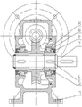
The utility model relates to a speed reducer, in particular to a speed reducer for a wood working machine, which mainly resolves the problems of the prior art that a case body of the speed reducer and a base are manufactured in split mode, the connection strength is poor, the speed reducer may be broken due to vibration, a power input source of the speed reducer is arranged below the speed reducer, operation is inconvenient and the like. The speed reducer for the wood working machine comprises a base (1) and a case body (2) which arranged on the upper portion of the base. The speed reducer for the wood working machine is characterized in that the base (1) and the case body (2) are integrated, the upper portion of the case body is connected with an input flange (3), a worm rod (4) is connected with the input flange in penetrating mode in the case body, the middle of the worm rod is meshed with a worm wheel (5), an output shaft (7) is fixed in the middle of the work wheel through a flat key (6), an end cover (8) is fixed on one side of the case body, and one end of the output shaft extends out of the end cover.
Description
Technical field
The utility model relates to a kind of speed reducer, especially relates to a kind of speed reducer that is used for woodworking machinery.
Background technique
At present; Miniature gear speed reducer, the worm-gear speed reducer of being used widely; Receive volume restrictions, its speed ratio is less than normal, and its transmission direction is generally parallel input output and can not satisfies some existing large speed ratios mini-plant that has vertical transmission direction to require again that slows down and install and use.Chinese patent discloses a kind of double worm and gear speed reducer structure (notice of authorization number: CN 201250880Y); It comprises worm type of reduction gearing; Be provided with two worm type of reduction gearings; Worm screw on two worm type of reduction gearings links together through the coupling of axial rotation adjustable angle, realizes synchronization; Have at least one worm screw two ends all to stretch out in himself reducer shell in two worm type of reduction gearings, with a end that coupling is not installed on this worm screw input shaft as this reducing gear; Output shaft on each worm type of reduction gearing is connected with a small gear respectively; Small gear simultaneously and the gearwheel engagement driving, and with the transmission shaft at gearwheel place output shaft as this reducing gear; The two ends of the worm screw of two worm type of reduction gearings all stretch out in the housing of retarder itself separately; Two worm type of reduction gearings and connected small gear respectively; Have identical specification respectively, the coupling of employed axial rotation adjustable angle is made up of two half-couplings, and some screws evenly distribute on one of them half-coupling; Corresponding described screw is provided with the slotted hole of some arcs on another half-coupling, is fastenedly connected through screw between two half-couplings.Process but the casing of this speed reducer separates with base, so join strength is relatively poor, in use because vibrations can produce fracture, and the power input source of speed reducer is positioned at the speed reducer below, and operation is inconvenience comparatively.
The model utility content
The utility model provides a kind of speed reducer that is used for woodworking machinery; It mainly is that the casing that solves the existing in prior technology speed reducer separates with base and processes; Therefore join strength is relatively poor; In use because vibrations can produce fracture, and the power input source of speed reducer is positioned at the speed reducer below, operates the technical problem of comparatively inconvenience etc.
The above-mentioned technical problem of the utility model mainly is able to solve through following technical proposals:
The speed reducer that is used for woodworking machinery of the utility model comprises base, and base top is provided with casing; Described base and casing integral body are processed, and the top of casing is connected with input flange, and box house, input flange cross-under have worm screw; The worm screw middle part is engaged with worm gear; Be fixed with output shaft through flat key in the middle of the worm gear, a side of casing is fixed with end cap, and output shaft one end stretches out outside the end cap.Behind the worm screw input power, promptly begin to rotate with the worm gear of its engagement, output shaft is given in last transmission, and output shaft can be connected with miscellaneous equipment through flat key.Base and casing integral body are processed, and can disposablely machine like this, and whole speed reducer casing can not produce fracture in use, and are positioned at the top of speed reducer as the input flange of power input source, operate comparatively easy.
As preferably, be provided with first tapered roller bearing between described worm screw two ends and the casing.Can make that like this worm screw is more smooth and easy rotatably.
As preferably, all be provided with second tapered roller bearing between described output shaft and casing, the end cap.Can make that like this output shaft is more smooth and easy rotatably.
As preferably, described input flange the inner is provided with first oil sealing.First oil sealing can prevent that the fluid in the casing from leaking outside, and also can prevent that the outside dust and other impurities of speed reducer from invading speed reducer inside simultaneously.
As preferably, the outer end of described end cap is provided with second oil sealing.Second oil sealing can prevent that the fluid in the casing from leaking outside, and also can prevent that the outside dust and other impurities of speed reducer from invading speed reducer inside simultaneously.
Therefore, the utility model is processed casing and base integral body, and the intensity of the speed reducer whole box body that is is stronger, can not meet accident during use, and input flange is placed the top of speed reducer, makes that operation is comparatively convenient, simple and reasonable for structure.
Description of drawings
Accompanying drawing 1 is a kind of structural representation of the utility model;
Accompanying drawing 2 is side structure schematic representation of Fig. 1.
Component, position and numbering among the figure: base 1, casing 2, input flange 3, worm screw 4, worm gear 5, flat key 6, output shaft 7, end cap 8, first tapered roller bearing 9, second tapered roller bearing 10, first oil sealing 11, second oil sealing 12.
Embodiment
Pass through embodiment below, and combine accompanying drawing, do further bright specifically the technological scheme of the utility model.
Embodiment: the speed reducer that is used for woodworking machinery of this example, like Fig. 1, Fig. 2, a base 1 is arranged, base top is provided with casing 2, and base and casing integral body are processed, and the top of casing is connected with input flange 3, and input flange the inner is provided with first oil sealing 11.Box house, input flange cross-under have worm screw 4, are provided with first tapered roller bearing 9 between worm screw two ends and the casing.The worm screw middle part is engaged with worm gear 5, is fixed with output shaft 7 through flat key 6 in the middle of the worm gear, and a side of casing is fixed with end cap 8, and the outer end of end cap is provided with second oil sealing 12, and output shaft one end stretches out outside the end cap.All be provided with second tapered roller bearing 10 between output shaft and casing, the end cap 8.
During use, worm screw 4 places input power, worm screw drives worm gear 5 rotations, and the output shaft 7 that worm gear connects is connected with miscellaneous equipment through flat key, can give miscellaneous equipment with transmission of power after the worm gear rotation.
The above is merely the specific embodiment of the utility model; But the structure characteristic of the utility model is not limited thereto; Any those skilled in the art is in the field of the utility model, and variation of being done or modification all are encompassed among the claim of the utility model.
Claims (5)
1. a speed reducer that is used for woodworking machinery comprises base (1), and base top is provided with casing (2); It is characterized in that described base (1) and casing (2) integral body processes, the top of casing is connected with input flange (3), and box house, input flange cross-under have worm screw (4); The worm screw middle part is engaged with worm gear (5); Be fixed with output shaft (7) through flat key (6) in the middle of the worm gear, a side of casing is fixed with end cap (8), and output shaft one end stretches out outside the end cap.
2. the speed reducer that is used for woodworking machinery according to claim 1 is characterized in that being provided with first tapered roller bearing (9) between described worm screw (4) two ends and the casing (1).
3. the speed reducer that is used for woodworking machinery according to claim 1 and 2 is characterized in that all being provided with second tapered roller bearing (10) between described output shaft (7) and casing (1), the end cap (8).
4. the speed reducer that is used for woodworking machinery according to claim 1 and 2 is characterized in that described input flange (3) the inner is provided with first oil sealing (11).
5. the speed reducer that is used for woodworking machinery according to claim 1 and 2 is characterized in that the outer end of described end cap (8) is provided with second oil sealing (12).
Priority Applications (1)
| Application Number | Priority Date | Filing Date | Title |
|---|---|---|---|
| CN2011202614300U CN202194997U (en) | 2011-07-22 | 2011-07-22 | Speed reducer for wood working machine |
Applications Claiming Priority (1)
| Application Number | Priority Date | Filing Date | Title |
|---|---|---|---|
| CN2011202614300U CN202194997U (en) | 2011-07-22 | 2011-07-22 | Speed reducer for wood working machine |
Publications (1)
| Publication Number | Publication Date |
|---|---|
| CN202194997U true CN202194997U (en) | 2012-04-18 |
Family
ID=45949909
Family Applications (1)
| Application Number | Title | Priority Date | Filing Date |
|---|---|---|---|
| CN2011202614300U Expired - Lifetime CN202194997U (en) | 2011-07-22 | 2011-07-22 | Speed reducer for wood working machine |
Country Status (1)
| Country | Link |
|---|---|
| CN (1) | CN202194997U (en) |
Cited By (2)
| Publication number | Priority date | Publication date | Assignee | Title |
|---|---|---|---|---|
| CN103075466A (en) * | 2013-01-10 | 2013-05-01 | 长治钢铁(集团)锻压机械制造有限公司 | Driving converging device of fast-to-mount veneer rolling machine |
| CN103075495A (en) * | 2013-01-10 | 2013-05-01 | 长治钢铁(集团)锻压机械制造有限公司 | Two-point support device of combined driving input gear |
-
2011
- 2011-07-22 CN CN2011202614300U patent/CN202194997U/en not_active Expired - Lifetime
Cited By (2)
| Publication number | Priority date | Publication date | Assignee | Title |
|---|---|---|---|---|
| CN103075466A (en) * | 2013-01-10 | 2013-05-01 | 长治钢铁(集团)锻压机械制造有限公司 | Driving converging device of fast-to-mount veneer rolling machine |
| CN103075495A (en) * | 2013-01-10 | 2013-05-01 | 长治钢铁(集团)锻压机械制造有限公司 | Two-point support device of combined driving input gear |
Similar Documents
| Publication | Publication Date | Title |
|---|---|---|
| CN205101472U (en) | Tertiary reduction gear of electric motor car | |
| CN108468759A (en) | A kind of petroleum drilling machine winch shift-variable formula planetary gear reduction box | |
| CN203560366U (en) | Multistage gear drive device | |
| CN202194997U (en) | Speed reducer for wood working machine | |
| CN202194999U (en) | Worm gear and worm reducer | |
| CN203686069U (en) | Speed reducer with stable transmission | |
| CN202195002U (en) | Speed reducer for an incubation device | |
| CN201753756U (en) | Speed reducer with multiple assembling forms | |
| CN201772023U (en) | Fully-closed type worm gear speed reducer | |
| CN202612486U (en) | Fracturing pump driving device for planetary reduction box | |
| CN202195003U (en) | Speed reducer for a wood working machine | |
| CN201027910Y (en) | Vertical output speed reducer with large transmission ratio | |
| CN202195001U (en) | Speed reducer for packaging machinery | |
| CN201753743U (en) | Worm gear speed reducing machine | |
| CN102979882A (en) | Machinery capable of saving labor and distance and work | |
| CN208295045U (en) | A kind of petroleum drilling machine winch shift-variable formula planetary gear reduction box | |
| CN202194998U (en) | Reducer for stone equipment | |
| CN201736117U (en) | Eccentric assembly of lapping machine main shaft | |
| CN202746492U (en) | Compact worm speed reducer | |
| CN202674175U (en) | Worm-and-gear reducer with output flange | |
| CN202195006U (en) | Speed reducer for high-voltage switch | |
| CN204061829U (en) | A kind of stockbreeding machine speed reducer of motor flange band bearing location | |
| CN202746493U (en) | Split-structured worm speed reducer | |
| CN201753744U (en) | Worm-gear worm speed reducer with input flange | |
| CN201772024U (en) | Worm wheel and worm reducer |
Legal Events
| Date | Code | Title | Description |
|---|---|---|---|
| C14 | Grant of patent or utility model | ||
| GR01 | Patent grant | ||
| CX01 | Expiry of patent term |
Granted publication date: 20120418 |
|
| CX01 | Expiry of patent term |