A kind of high-pressure air source generation equipment
Technical field the utility model relates to field of mechanical technique, particularly high-pressure air source generation equipment.
Background technique high-pressure air source generation equipment is to be medium with pressurized air; With motor or petrol engine is power source; Self-braking a kind of equipment after supercharging reaches required pressure, it is widely used in industry-by-industries such as machine building industry, auto manufacturing, the production automation.Existing high-pressure air source generation equipment mainly is to use the pressurized air of 0.6-0.8MP to be medium, and pressurized air carries out secondary booster through air operated reversing valve promotion cylinder and reaches needed high pressure, but owing to contain than more moisture content under atmospheric pressure in the pressurized air; In the working procedure of equipment; Along with the increase of pressure, airborne moisture content congeals into ice and can freeze to death air operated reversing valve or block, and directly influences machinery action; Cause the equipment can't proper functioning; This phenomenon is particularly serious in winter, and frequent the moving back and forth of cylinder, and its Sealing easy abrasion results in pressure is not come up.
The purpose of summary of the invention the utility model provides a kind of high-pressure air source generation equipment, and this high-pressure air source generation equipment is to propose a solution to the problem that exists in the background technique, has advantages such as simple in structure, efficient height and energy-conserving and environment-protective.
The purpose of the utility model realizes through following technological scheme: a kind of high-pressure air source generation equipment; Comprise master control system and compression system; Master control system and compression system connect through data/address bus; By master control system control compression system as required pressure-activated with stop, it is characterized in that compression system comprises compression motor, one-level compression set, secondary compression set, three grades of compression sets, water and oil separator, pressure maintaining valve, safety check, gas charging valve, gas-charging connection, air pressure detector, Decompression valves, gas holder;
Said one-level compression set and secondary compression set comprise compression valve and cooling tube in the technique scheme;
The cooling tube of said secondary compression set connects water and oil separator through pipeline in the technique scheme, and the lower end mouth of water and oil separator is provided with compression gas bleeder valve and the disappointing flexible pipe of condensation;
Said three grades of compression sets comprise termination safety valve and last condensation tube in the technique scheme;
The last condensation tube of said three grades of compression sets connects water and oil separator through pipeline in the technique scheme, and the lower end mouth of water and oil separator is provided with compression Decompression valves and compression relief tube.
The basic ideas of technique scheme are that master control system detects the lower range whether the gas holder air pressure is lower than setting pressure after the device power, if gas holder pressure does not have in the lower range of setting, master control system can not start; Along with the pressure of compressed-air actuated continuous use gas holder constantly reduces; Prescribe a time limit when being reduced to the following of setting, master control system control compression system starts the beginning supercharging, when pressure rises to the upper pressure limit of setting; Master control system control compression system stops; So circulation produces and additional new pressurized gas, keeps the stable of bleed pressure.
The advantage of this high-pressure air source generation equipment has: 1, performance simple in structure is stable; 2, the automation control system of self design has very high cost performance; 3, medium is a normal air and different use pressurized air to be medium with market, energy-conserving and environment-protective; 4, bleed pressure is stable, and flow is big.
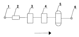
Description of drawings Fig. 1 is the structural representation of existing high-pressure air source generation equipment.
Fig. 2 is the structure schematic flow sheet of existing high-pressure air source generation equipment.
Fig. 3 is the structural representation of the utility model.
Fig. 4 is the structure schematic flow sheet of the utility model compression system.
Among the figure, suction port (1), air operated reversing valve (2), one-level compression cylinder (3), secondary compression cylinder (4), gas holder (5), air outlet (6), air inlet filter core (7), one-level compression (8), one-level compressing secure valve (9), secondary compression (10), pressure maintaining valve (11), safety check (12), gas charging valve (13), gas-charging connection (14), Decompression valves (15), air pressure detector (16), master control system (17), compression motor (18), one-level compression set (19), secondary compression set (20), three grades of compression sets (21), compression valve (22), cooling tube (23), water and oil separator (24), compression gas bleeder valve (25), the disappointing flexible pipe (26) of condensation, three grades of compressions (27), termination safety valve (28), last condensation tube (29), compression Decompression valves (30) and compression relief tube (31).
Embodiment is described further the utility model below in conjunction with accompanying drawing and embodiment.
Fig. 3 is the structural representation of the utility model; Comprise master control system (17), suction port (1), compression motor (18), one-level compression set (19), secondary compression set (20), three grades of compression sets (21), gas holder (5) and air outlet (6); The utility model is to be medium with the air; With compression motor (18) is power source, and master control system (17) control compression motor (18) stops after three grades of superchargings reach required pressure according to the startup that needs of gas holder (5) air pressure automatically.
Fig. 4 is the structure schematic flow sheet of the utility model compression system; Suction port (1) at compression system is connected with air inlet filter core (7); Be provided with compression valve (22) and cooling tube (23) in one-level compression set (19) and the secondary compression set (20); Be provided with in three grades of compression sets (21) and stop safety valve (27) and last condensation tube (28); The cooling tube (23) of secondary compression set (20) connects water and oil separator (24) through pipeline, and the lower end mouth of water and oil separator (24) is provided with compression gas bleeder valve (25) and the disappointing flexible pipe (26) of condensation; The last condensation tube (28) of three grades of compression sets (21) connects water and oil separator (24) through pipeline; The lower end mouth of water and oil separator (24) is provided with compression Decompression valves (29) and compression relief tube (30), and three grades of compression sets (21) water and oil separators (24) connect pressure maintaining valve (11), safety check (12), gas charging valve (13), gas-charging connection (14), air pressure detector (15) and Decompression valves (16) through pipeline.
In practical operation; After the high-pressure air source generation device power; Whether the air pressure in master control system (17) the detection gas holder (5) is lower than the lower range of setting pressure, if gas holder (5) pressure does not have in the lower range of setting, master control system (17) can not start so; Along with the pressure of compressed-air actuated continuous use gas holder (5) constantly reduces; When being lower than the lower range of setting pressure, master control system (17) control compression system starts the beginning supercharging, when pressure rises to the upper pressure limit of setting; Master control system (17) control compression system stops; So circulation produces and additional new pressurized gas, keeps the stable of bleed pressure.
Test shows, this high-pressure air source generation equipment, and performance simple in structure is stable, and very high cost performance, its medium are arranged is normal air and the pressurized air that uses on different and the market is medium, so it also is the supercharging equipment of very energy-conserving and environment-protective.