CN202165260U - Hydraulic pump - Google Patents
Hydraulic pump Download PDFInfo
- Publication number
- CN202165260U CN202165260U CN2011202530150U CN201120253015U CN202165260U CN 202165260 U CN202165260 U CN 202165260U CN 2011202530150 U CN2011202530150 U CN 2011202530150U CN 201120253015 U CN201120253015 U CN 201120253015U CN 202165260 U CN202165260 U CN 202165260U
- Authority
- CN
- China
- Prior art keywords
- piston
- hydraulic pump
- valve body
- liquid outlet
- fluid intake
- Prior art date
- Legal status (The legal status is an assumption and is not a legal conclusion. Google has not performed a legal analysis and makes no representation as to the accuracy of the status listed.)
- Expired - Fee Related
Links
Images

Abstract
The utility model relates to the technical field of hydraulic elements, in particular to a hydraulic pump, which is provided with a seat, a piston and a rotating piece, wherein the seat is provided with a hydraulic working cavity, a liquid suction opening and a liquid output opening, the liquid suction opening and the liquid output opening are communicated with the hydraulic working cavity, the piston can reciprocate in the hydraulic working cavity to achieve liquid pumping, the piston is installed in the hydraulic working cavity on the base in embedding mode, and the rotating piece can drive the piston to reciprocate through rotation. A connecting piece is arranged between the rotating piece and the piston in sleeving mode, a rail groove rising and falling along the reciprocating direction of the piston and a steel ball capable of rolling in the rail groove are arranged on the sleeving position of the rotating piece and the piston, and the rail groove and the steel ball are matched with each other and arranged on the rotating piece and the piston correspondingly. The hydraulic pump changes rotating movement to linear movement through matching between the rotating piece and the piston so as to achieve suction-in and pump-out work of reciprocating of the piston. The hydraulic pump is simple in structure, reasonable, scientific, low in investment cost, convenient to maintain and capable of greatly improving utilization rate of a product and prolonging service life.
Description
Technical field
The utility model relates to technical field of hydraulic elements, especially relates to a kind of oil hydraulic pump.
Background technique
At present; In common hydraulic control system and the circulation loop system, combine external one-way valve and various pipeline parts to install by gear pump or vane pump mostly and form, this structure exists manufacture cost high; The pump housing is easy to wear; Life-span is short, and external one-way valve is prone to situation such as obstruction, and these all greatly influence the normal use of system.
For this reason, the applicant is because above-mentioned convention hydraulic element defective and inconvenience are being adhered to the spirit that research is innovated, kept on improving; Utilize its professional eye and professional knowledge; Work out a kind of accords with industrial utilization, making is easy, cost of investment is low, the oil hydraulic pump of long service life.
Summary of the invention
It is a kind of simple in structure, scientific and reasonable that the purpose of the utility model is to provide, and makes to be easy to oil hydraulic pump.
The utility model purpose again provides a kind of oil hydraulic pump of built-in one-way valve, and one-way valve is difficult for stopping up.
For achieving the above object, the utility model adopts following technological scheme:
A kind of oil hydraulic pump has:
Fluid intake and liquid outlet that one base, base are provided with the hydraulic work chamber and are communicated with the hydraulic work chamber;
One can be in the hydraulic work chamber of base to-and-fro motion and realize the piston of sucking pump liquid, piston is flush-mounted in the hydraulic work chamber of base;
One can be through rotating the reciprocating rotating component of driven plunger.
The sheathed connection between said rotating component and the piston, and be provided with along the rail slot of reciprocating motion of the pistons direction fluctuation and the steel ball that can in rail slot, roll in both sheathed positions, rail slot and matching property of steel ball correspondence are arranged on rotating component and the piston.
Said fluid intake and liquid outlet be for vertically offering, and in fluid intake and liquid outlet, be provided with the valve body of utilization from resealing.
Said fluid intake is for vertically offer down; In the passage in the inboard of fluid intake connection hydraulic work chamber, be formed with the step position; Valve body is steel ball or glass marble, and valve body compresses and is parked on the step position and the through hole at place, sealed step position, reaches deadweight seal fluid suction port; Also be provided with in the fluid intake one can limit the valve body vertical up-or-down movement inside casing, inside casing is for embedding combination or making with the fluid intake moulding.
Said liquid outlet is for vertically offer up; In the passage in the inboard of liquid outlet connection hydraulic work chamber, be formed with the step position; Valve body is steel ball or glass marble, and valve body compresses and is parked on the step position and the through hole at place, sealed step position, reaches deadweight seal fluid delivery outlet; Also be provided with in the liquid outlet one can limit the valve body vertical up-or-down movement inside casing, inside casing is for embedding combination or making with the liquid outlet moulding.
The section of said rail slot is the corrugation shape, and rail slot is provided with one or more.
The utility model is a straight line motion through cooperating the realization rotational motion between rotating component and the piston, thereby reaches the suction of reciprocating motion of the pistons and pump work, and is simple in structure; Scientific and reasonable; Cost of investment is low, and is easy to maintenance, promotes the utilization rate and the working life of product greatly.
The utility model advantage again is in fluid intake and liquid outlet, to adopt from resealing, is built-in structure, good integrity; Valve body is from resealing, and flexibility is good, reduces dirt and deposits in sealing part; The dirt that is deposited influences little; Keep the gateway unimpeded, long service life has overcome the defective that conventional thin membrane type one-way valve is subject to the dirt shutoff.
Description of drawings:
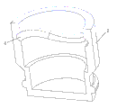
Accompanying drawing 1 is the utility model one of which embodiment form structure schematic representation;
Accompanying drawing 3 is the embodiment's of Fig. 1 a piston inner structure schematic representation.
Embodiment:
Below in conjunction with accompanying drawing the utility model is further specified:
Consult Fig. 1, shown in 2, be to be the utility model preferred embodiment schematic representation; The relevant a kind of oil hydraulic pump of the utility model, this oil hydraulic pump has a base 1, fluid intake 12 and liquid outlet 13 that base 1 is provided with hydraulic work chamber 11 and is communicated with hydraulic work chamber 11; One can be in the hydraulic work chamber 11 of base to-and-fro motion and realize the piston 2 of sucking pump liquid, piston 2 is flush-mounted in the hydraulic work chamber 11 of base; One can be through rotating driven plunger 2 reciprocating rotating components 3, and rotating component 3 is by motor 7 rotary driving.
Fig. 1,2, shown in 3; In the present embodiment; The sheathed connection between said rotating component 3 and the piston 2, the form of cover or overcoat connected piston 2 in rotating component 3 can adopt, among the figure in the mesopore of embodiment's rotating component 3 through interior cover form embedding piston 2; And being provided with rail slot 4 that rises and falls along piston 2 vibration-directions and the steel ball 5 that can rail slot 4 in, roll in both sheathed positions, rail slot 4 and steel ball 5 matching property correspondences are arranged on rotating component 3 and the piston 2.Embodiment's rail slot 4 is opened on the madial wall of piston 2 mesopores among the figure, and steel ball 5 is embedded on the outer circumferential face of rotating component 3, and steel ball 5 is a symmetric design, makes stressed steady.The section of rail slot 4 is the corrugation shape, makes steel ball 5 when rail slot 4 moves, can obtain better driving power and drives piston 2 to-and-fro motion, and effectively reduce the surface friction drag between steel ball 5 and the rail slot 4.The embedded end of piston 2 is provided with corresponding seal ring, to realize that piston 2 sucks and pump liquid in the hydraulic work chamber 11 of base.Also be provided with the guide and limit structure of guaranteeing piston 2 linear reciprocating motions within the outer side wall of piston 2 and the hydraulic work chamber 11 between the sidewall; Be provided with steel ball and sidewall line channel within hydraulic work chamber 11 like outer side wall at piston 2; Cooperate with line channel with steel ball to guarantee that piston 2 does linear reciprocating motion in the hydraulic work chamber 11 of base, realize that thus rotating component 3 rotates driven plunger 2 to-and-fro motion.In the present embodiment, rail slot 4 is provided with one, also can on the madial wall of piston 2 mesopores, be provided with many rail slots 4 according to need of work certainly, and the fluctuating of many rail slots 4 can be synchronous or asynchronous.
During work; Motor 7 drives rotating component 3 rotations; 5 of steel balls on rotating component 3 outer circumferential faces move in rail slot 4 because rail slot 4 fluctuations, and rotating component 3 in the axial direction relative fixed on base 1; Be that steel ball 5 capable of using obtains driving force and drives piston 2 to-and-fro motion like this when rail slot 4 moves; Make piston 2 to-and-fro motion and reach and suck and pump work in the hydraulic work chamber 11 of base, cooperate the fluid intake 12 and liquid outlet 13 of base 1, can realize hydraulic control and circulation that liquid sucks and pumps.
Shown in Figure 2, in the present embodiment, described fluid intake 12 and liquid outlet 13 be for vertically offering, and in fluid intake 12 and liquid outlet 13, be provided with the valve body 6 of utilization from resealing.Valve body 6 built-in designs, structural good, conveniently install and use.Fluid intake 12 is for vertically offer down; In the passage in the inboard of fluid intake 12 connection hydraulic work chamber 11, be formed with step position 121; Valve body 6 is steel ball or glass marble; Valve body 6 compresses and is parked on the step position 121 and the through hole at 121 places, sealed step position, reaches deadweight seal fluid suction port 12.And liquid outlet 13 is for vertically offer up; In the passage in the inboard of liquid outlet 13 connection hydraulic work chamber 11, be formed with step position 131; Valve body 6 is steel ball or glass marble; Valve body 6 compresses and is parked on the step position 131 and the through hole at 131 places, sealed step position, reaches deadweight seal fluid delivery outlet 13.
Shown in Figure 2; For effective management and control valve body 6; In fluid intake 12, also be provided with one can limit valve body 6 vertical up-or-down movements inside casing 122; And in liquid outlet 13, also be provided with one can limit valve body 6 vertical up-or-down movements inside casing 132, inside casing 122,132 for embed combination or make with fluid intake 12, liquid outlet 13 moulding respectively.Certainly, just wherein preferred embodiment of box form is not limited to this structure in being provided with, other structural type, and as designing V-arrangement guide port etc., as long as effectively management and control valve body 6 is from resealing, the structure that all should belong to the utility model effectively changes.In the present embodiment, also can be provided with the seal ring auxiliary seal from the position of resealing, reduce noise, increase sealing effect at valve body 6.
During work, when fluid intake 12 sucked, the pressure of generation was pushed the valve body 6 in the fluid intake 12 automatically open with outside liquid in piston 2 motion, and outside liquid can enter in the hydraulic work chamber 11 of base from fluid intake 12; Piston 2 is reversing motion liquid in the pump pressure hydraulic work chamber 11 then again; At this moment; Valve bodies 6 in the fluid intake 12 utilize deadweight and pressurized and seal fluid suction port 12; 6 of valve bodies in the opposite liquid outlet 13 are opened by thrust, and hydraulic work chamber 11 interior liquid are pumped from liquid outlet 13, realize hydraulic control and periodic duty.
The utility model is a straight line motion through cooperating the realization rotational motion between rotating component and the piston; Thereby reach the suction of reciprocating motion of the pistons and pump work, and resulting structure design realization employing is simple in structure from the built-in one-way valve structures of resealing; Scientific and reasonable; Cost of investment is low, and is easy to maintenance, promotes the utilization rate and the working life of product greatly.The utility model overcomes the hydraulic system defective that conventional tooth wheel pump or vane pump combine external one-way valve and various pipeline parts to form applicable in various hydraulic control systems and the circulation loop system.
Certainly, more than diagram is merely the utility model preferred embodiments, is not the using scope that limits the utility model with this, so every on the utility model principle, making in the protection domain that equivalent change all should be included in the utility model.
Claims (8)
1. an oil hydraulic pump is characterized in that: have
Fluid intake (12) and liquid outlet (13) that one base (1), base (1) are provided with hydraulic work chamber (11) and are communicated with hydraulic work chamber (11);
One can be in the hydraulic work chamber (11) of base to-and-fro motion and realize the piston (2) of sucking pump liquid, piston (2) is flush-mounted in the hydraulic work chamber (11) of base;
One can be through rotating the reciprocating rotating component of driven plunger (2) (3).
2. a kind of oil hydraulic pump according to claim 1; It is characterized in that: the sheathed connection between said rotating component (3) and the piston (2); And being provided with rail slot (4) that rises and falls along piston (2) vibration-direction and the steel ball (5) that can in rail slot (4), roll in both sheathed positions, rail slot (4) and steel ball (5) matching property correspondence are arranged on rotating component (3) and the piston (2).
3. a kind of oil hydraulic pump according to claim 1; It is characterized in that: said fluid intake (12) and liquid outlet (13) be for vertically offering, and in fluid intake (12) and liquid outlet (13), be provided with the valve body (6) of utilization from resealing.
4. a kind of oil hydraulic pump according to claim 3; It is characterized in that: fluid intake (12) is for vertically offer down;, the inboard of fluid intake (12) is formed with step position (121) in connecting the passage in hydraulic work chamber (11); Valve body (6) is steel ball or glass marble, and valve body (6) compresses and is parked in the through hole that go up step position (121) and sealed step position (121) is located, and reaches deadweight seal fluid suction port (12).
5. a kind of oil hydraulic pump according to claim 3; It is characterized in that: liquid outlet (13) is for vertically offer up;, the inboard of liquid outlet (13) is formed with step position (131) in connecting the passage in hydraulic work chamber (11); Valve body (6) is steel ball or glass marble, and valve body (6) compresses and is parked in the through hole that go up step position (131) and sealed step position (131) is located, and reaches deadweight seal fluid delivery outlet (13).
6. a kind of oil hydraulic pump according to claim 2 is characterized in that: the section of rail slot (4) is the corrugation shape, and rail slot (4) is provided with one or more.
7. a kind of oil hydraulic pump according to claim 4; It is characterized in that: also be provided with in the fluid intake (12) one can limit valve body (6) vertical up-or-down movement inside casing (122), inside casing (122) is for embedding combination or making with fluid intake (12) moulding.
8. a kind of oil hydraulic pump according to claim 5; It is characterized in that: also be provided with in the liquid outlet (13) one can limit valve body (6) vertical up-or-down movement inside casing (132), inside casing (132) is for embedding combination or making with liquid outlet (13) moulding.
Priority Applications (1)
| Application Number | Priority Date | Filing Date | Title |
|---|---|---|---|
| CN2011202530150U CN202165260U (en) | 2011-07-18 | 2011-07-18 | Hydraulic pump |
Applications Claiming Priority (1)
| Application Number | Priority Date | Filing Date | Title |
|---|---|---|---|
| CN2011202530150U CN202165260U (en) | 2011-07-18 | 2011-07-18 | Hydraulic pump |
Publications (1)
| Publication Number | Publication Date |
|---|---|
| CN202165260U true CN202165260U (en) | 2012-03-14 |
Family
ID=45801089
Family Applications (1)
| Application Number | Title | Priority Date | Filing Date |
|---|---|---|---|
| CN2011202530150U Expired - Fee Related CN202165260U (en) | 2011-07-18 | 2011-07-18 | Hydraulic pump |
Country Status (1)
| Country | Link |
|---|---|
| CN (1) | CN202165260U (en) |
Cited By (5)
| Publication number | Priority date | Publication date | Assignee | Title |
|---|---|---|---|---|
| CN106593801A (en) * | 2017-01-16 | 2017-04-26 | 黄增 | Hydraulic pump reciprocating rotary type steel ball transmission mechanism |
| CN106704136A (en) * | 2017-01-16 | 2017-05-24 | 黄增 | Single-plunger double-displacement reciprocating rotation hydraulic drive |
| CN106762513A (en) * | 2017-01-16 | 2017-05-31 | 黄增 | The single amount progressive rotation type hydraulic unit driver of single plunger |
| WO2019020063A1 (en) * | 2017-07-26 | 2019-01-31 | 施育秧 | Liquid pumping device |
| CN113719439A (en) * | 2021-08-24 | 2021-11-30 | 浙江千机智能科技有限公司 | Transmission structure, transmission connection mechanism and air compressor |
-
2011
- 2011-07-18 CN CN2011202530150U patent/CN202165260U/en not_active Expired - Fee Related
Cited By (6)
| Publication number | Priority date | Publication date | Assignee | Title |
|---|---|---|---|---|
| CN106593801A (en) * | 2017-01-16 | 2017-04-26 | 黄增 | Hydraulic pump reciprocating rotary type steel ball transmission mechanism |
| CN106704136A (en) * | 2017-01-16 | 2017-05-24 | 黄增 | Single-plunger double-displacement reciprocating rotation hydraulic drive |
| CN106762513A (en) * | 2017-01-16 | 2017-05-31 | 黄增 | The single amount progressive rotation type hydraulic unit driver of single plunger |
| WO2019020063A1 (en) * | 2017-07-26 | 2019-01-31 | 施育秧 | Liquid pumping device |
| US11187228B2 (en) | 2017-07-26 | 2021-11-30 | Yuyang SHI | Liquid pumping device with concave caves and convex liquid extruding component |
| CN113719439A (en) * | 2021-08-24 | 2021-11-30 | 浙江千机智能科技有限公司 | Transmission structure, transmission connection mechanism and air compressor |
Similar Documents
| Publication | Publication Date | Title |
|---|---|---|
| CN202165260U (en) | Hydraulic pump | |
| CN103883520A (en) | Rotor type immersible pump with eccentric shaft directly connected with motor | |
| CN103438006B (en) | Miniature hot-water recycle pump | |
| CN201998235U (en) | Oil pump for chain saw | |
| CN204738961U (en) | Variable type gear pump | |
| CN101985930B (en) | Rotor type deep submersible pump | |
| CN115559876A (en) | Motor shaft two-dimensional piston integrated motor pump | |
| KR20110115261A (en) | Bellows pump for a warm-water mat | |
| CN202220633U (en) | Gear transmission rotor oil pump connected with an end cover of an engine | |
| CN208634001U (en) | A kind of vector controlled pump | |
| CN204961191U (en) | Novel slush pump based on screw drive | |
| CN204267280U (en) | A kind of Roots water pump of water lubrication gear | |
| CN104500363B (en) | There is the plunger displacement pump of lubricating system | |
| CN204283874U (en) | Marine gear pump | |
| CN209892442U (en) | Bidirectional fluid pump | |
| CN204153438U (en) | The oil pump assembly of motor | |
| CN208901053U (en) | A kind of rotor-type oil pump can be reduced abrasion | |
| CN202628504U (en) | Positive displacement single-vane hydraulic pump | |
| CN202851437U (en) | Friction seal device for pump | |
| CN103363277B (en) | A kind of oil pump, engine front cover lid and motor | |
| CN215256767U (en) | Long service life's gear metering pump | |
| CN208966566U (en) | A kind of novel lobe pump | |
| CN206299525U (en) | A kind of low noise cam-type axial piston pump | |
| CN201162721Y (en) | Pump housing synchronous revolution type flow guiding fluid pump | |
| CN101865128A (en) | Screw rod type electric oil fuel pump |
Legal Events
| Date | Code | Title | Description |
|---|---|---|---|
| C14 | Grant of patent or utility model | ||
| GR01 | Patent grant | ||
| C17 | Cessation of patent right | ||
| CF01 | Termination of patent right due to non-payment of annual fee |
Granted publication date: 20120314 Termination date: 20130718 |