CN202156808U - Coating rolling device capable of splitting - Google Patents
Coating rolling device capable of splitting Download PDFInfo
- Publication number
- CN202156808U CN202156808U CN2011201775220U CN201120177522U CN202156808U CN 202156808 U CN202156808 U CN 202156808U CN 2011201775220 U CN2011201775220 U CN 2011201775220U CN 201120177522 U CN201120177522 U CN 201120177522U CN 202156808 U CN202156808 U CN 202156808U
- Authority
- CN
- China
- Prior art keywords
- rolling wheel
- coating
- rolling
- winding wheel
- cutter shaft
- Prior art date
- Legal status (The legal status is an assumption and is not a legal conclusion. Google has not performed a legal analysis and makes no representation as to the accuracy of the status listed.)
- Expired - Lifetime
Links
Images
Abstract
The utility model discloses a coating rolling device capable of splitting, including a frame having two horizontally and symmetrically distributed support arms (5), and a rolling wheel group across between the two support arms, the rolling wheel group includes a first rolling wheel, a second rolling wheel, a third rolling wheel, and a fourth rolling wheel (1, 2, 3, 4) which are arranged side by side, the coating to be rolled (6) is passed through the bottom of the first rolling wheel, the top of the second rolling wheel, the bottom of the third rolling wheel, the top of the fourth rolling wheel successively; a knife mounting shaft (7) parallel to the fourth rolling wheel is arranged between the third rolling wheel and the fourth rolling wheel, the two ends of the knife mounting shaft are respectively connected and fixed with the two support arms, at least one knife mounting jig (8) is arranged on the knife mounting shaft, and a splitting cutter (9) is fixed at the lower end of the knife mounting jig. Compared with the prior art, The device provided splits the coating into products in various widths whiling rolling the coating and rolls synchronously without the need for a secondary machining, thereby saving a large amount of manpower and material resources.
Description
Technical field
The utility model relates to the coating processing equipment, relates in particular to a kind of coating wrap-up with the function of cutting.
Background technology
To carry out rolling after being coated on operations such as accomplishing gluing, oven dry, after intact one whole of rolling, cut at another equipment as required again, form the product of different in width.So work efficiency is not high, has wasted a large amount of manpowers and material resources.Need a kind of coating wrap-up of cutting processing of in the coating of rolling, just accomplishing in the industry badly.
The utility model content
The utility model is the problems referred to above that will solve prior art, proposes a kind of coating wrap-up with the function of cutting.
For solving the problems of the technologies described above; The technical scheme that the utility model proposes is a kind of coating wrap-up with the function of cutting of design; Comprise frame with hold-down arm that two horizontal symmetrical distribute, across the rolling wheels between two hold-down arms; Said rolling wheels comprise first, second, third, fourth winding wheel side by side, by rolling coating successively from first winding wheel bottom, bottom the second winding wheel top, the 3rd winding wheel, the 4th winding wheel top passes; Between the 3rd, the 4th winding wheel, be provided with a frame cutter shaft parallel with the 4th winding wheel, it is fixing that these cutter shaft two ends are connected with described two hold-down arms respectively, and the frame cutter shaft is provided with at least one frame tool holding device, and said tool holding device lower end be cutting tool fixedly.
Said tool holding device fixed through check screw and frame cutter shaft, and can axially move along the frame cutter shaft.
Said cutter shaft is provided with scale graduation.
Compared with prior art, the utility model cuts into coating the product of multiple width in rolling coating, and rolling synchronously, does not need to pass through secondary processing again, saves a large amount of manpowers and material resources.
Description of drawings
Below in conjunction with accompanying drawing and embodiment the utility model is made detailed explanation, wherein:
Fig. 1 is the stereo appearance figure of prior art;
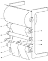
Fig. 2 is the stereo appearance figure of the utility model preferred embodiment.
The specific embodiment
The utility model discloses a kind of coating wrap-up with the function of cutting; Comprise frame with hold-down arm 5 that two horizontal symmetrical distribute, across the rolling wheels between two hold-down arms; Said rolling wheels comprise first, second, third, fourth winding wheel 1,2,3,4 side by side, by rolling coating 6 successively from first winding wheel bottom, bottom the second winding wheel top, the 3rd winding wheel, the 4th winding wheel top passes; Between the 3rd, the 4th winding wheel, be provided with a frame cutter shaft 7 parallel with the 4th winding wheel; These cutter shaft two ends are connected fixing respectively with described two hold-down arms; The frame cutter shaft is provided with at least one frame tool holding device 8, and said tool holding device lower end be cutting tool 9 fixedly.
Fig. 1 shows the stereo appearance figure of prior art; Prior art is directly carried out rolling after accomplishing operations such as gluing, oven dry, after intact one whole of rolling, cutting with another equipment as required again; Form the product of different in width, so production efficiency is not high.Referring to the stereo appearance figure of the utility model preferred embodiment shown in Fig. 2, winding motor is positioned at left side (not drawing), and the rolling wheels keep tension force, makes the coating rolling smooth, and the cutting tool 8 on the frame cutter shaft will be coated with branch and cut, and then be dragged to the left side rolling.So do not need to cut processing through secondary again, improved effect, save a large amount of manpowers and material resources.In preferred embodiment, the frame tool holding device is fixing through check screw and frame cutter shaft 7, and can axially move along the frame cutter shaft.The frame tool holding device can be installed a plurality of simultaneously, can divide simultaneously to cut out a plurality of products.The frame cutter shaft is provided with scale graduation, regulates with the handled easily workman and cuts width.
Above embodiment is merely casehistory, non-providing constraints.Anyly do not break away from spirit of the present invention and category, and, all should be contained among the application's the claim scope its equivalent modifications of carrying out or change.
Claims (3)
1. coating wrap-up with the function of cutting; Comprise frame with hold-down arm (5) that two horizontal symmetrical distribute, across the rolling wheels between two hold-down arms; Said rolling wheels comprise first, second, third, fourth winding wheel (1,2,3,4) side by side; By rolling coating (6) successively from first winding wheel bottom, bottom the second winding wheel top, the 3rd winding wheel, the 4th winding wheel top passes; It is characterized in that: between the 3rd, the 4th winding wheel, be provided with a frame cutter shaft (7) parallel with the 4th winding wheel; It is fixing that these cutter shaft two ends are connected with described two hold-down arms respectively, and the frame cutter shaft is provided with at least one frame tool holding device (8), and said tool holding device lower end be cutting tool (9) fixedly.
2. coating wrap-up as claimed in claim 1 is characterized in that: said tool holding device is fixing through check screw and frame cutter shaft (7), and can axially move along the frame cutter shaft.
3. coating wrap-up as claimed in claim 2 is characterized in that: said cutter shaft is provided with scale graduation.
Priority Applications (1)
| Application Number | Priority Date | Filing Date | Title |
|---|---|---|---|
| CN2011201775220U CN202156808U (en) | 2011-05-30 | 2011-05-30 | Coating rolling device capable of splitting |
Applications Claiming Priority (1)
| Application Number | Priority Date | Filing Date | Title |
|---|---|---|---|
| CN2011201775220U CN202156808U (en) | 2011-05-30 | 2011-05-30 | Coating rolling device capable of splitting |
Publications (1)
| Publication Number | Publication Date |
|---|---|
| CN202156808U true CN202156808U (en) | 2012-03-07 |
Family
ID=45764450
Family Applications (1)
| Application Number | Title | Priority Date | Filing Date |
|---|---|---|---|
| CN2011201775220U Expired - Lifetime CN202156808U (en) | 2011-05-30 | 2011-05-30 | Coating rolling device capable of splitting |
Country Status (1)
| Country | Link |
|---|---|
| CN (1) | CN202156808U (en) |
Cited By (2)
| Publication number | Priority date | Publication date | Assignee | Title |
|---|---|---|---|---|
| CN105752728A (en) * | 2016-04-25 | 2016-07-13 | 句容东发生活用品有限公司 | Paper reeling machine with cutting positions adjustable |
| CN105800358A (en) * | 2016-04-29 | 2016-07-27 | 句容市恒盛电子水表厂 | Movably-installed paper winding machine |
-
2011
- 2011-05-30 CN CN2011201775220U patent/CN202156808U/en not_active Expired - Lifetime
Cited By (2)
| Publication number | Priority date | Publication date | Assignee | Title |
|---|---|---|---|---|
| CN105752728A (en) * | 2016-04-25 | 2016-07-13 | 句容东发生活用品有限公司 | Paper reeling machine with cutting positions adjustable |
| CN105800358A (en) * | 2016-04-29 | 2016-07-27 | 句容市恒盛电子水表厂 | Movably-installed paper winding machine |
Similar Documents
| Publication | Publication Date | Title |
|---|---|---|
| CN204449462U (en) | A kind of multi-angle bead cutter device with left and right stop | |
| CN103600865A (en) | Automatic edge covering device and method for PCB (printed circuit board) | |
| CN205166395U (en) | Be used for metal sheet parts machining device | |
| CN202593947U (en) | Automatic paper spreading device | |
| CN202156808U (en) | Coating rolling device capable of splitting | |
| CN104351287A (en) | Noodle cutting device | |
| CN102640800B (en) | Automatic paper paving device | |
| CN202106425U (en) | Die cutting machine | |
| CN204273068U (en) | A kind of noodle cutting device | |
| CN202399643U (en) | Ink-jet printing laser processing all-in-one machine | |
| CN204280852U (en) | Strip device is cut out in the winding of brake collar film | |
| CN203512106U (en) | Automatic edge covering device for PCB | |
| CN203843939U (en) | Solid batten forming machine | |
| CN203234028U (en) | Tipping paper curling device for YJ27 cigarette assembling machine | |
| CN202318393U (en) | Cutter system | |
| CN202824255U (en) | Leveling machine | |
| CN202214069U (en) | Splitting and folding machine for automatically tacking adhesive | |
| CN203766127U (en) | Double corrugated paper machine cutting system | |
| CN204079042U (en) | A kind of two roller arrangement | |
| CN204149240U (en) | Guillotine tool rest group | |
| CN202416028U (en) | Idler wheel structure of cutting machine | |
| CN203994855U (en) | A kind of knife combination frame | |
| CN102894027A (en) | Noodle cutting machine | |
| CN202897634U (en) | Splitting device applied to web slitter machine | |
| CN203600220U (en) | Plate cutting and arrangement bracket |
Legal Events
| Date | Code | Title | Description |
|---|---|---|---|
| C14 | Grant of patent or utility model | ||
| GR01 | Patent grant | ||
| CX01 | Expiry of patent term |
Granted publication date: 20120307 |
|
| CX01 | Expiry of patent term |