CN202133950U - Cooling base with slidable fan - Google Patents
Cooling base with slidable fan Download PDFInfo
- Publication number
- CN202133950U CN202133950U CN201120219528U CN201120219528U CN202133950U CN 202133950 U CN202133950 U CN 202133950U CN 201120219528 U CN201120219528 U CN 201120219528U CN 201120219528 U CN201120219528 U CN 201120219528U CN 202133950 U CN202133950 U CN 202133950U
- Authority
- CN
- China
- Prior art keywords
- fan
- base
- cooling base
- utility
- model
- Prior art date
- Legal status (The legal status is an assumption and is not a legal conclusion. Google has not performed a legal analysis and makes no representation as to the accuracy of the status listed.)
- Expired - Fee Related
Links
Images
Abstract
The utility model discloses a cooling base with a slidable fan, which is characterized in that the cooling base comprises a base (4), wherein the base (4) is provided with a ditch-type netted lines (3) on one side; a slidable fan(2) is arranged in the ditch-type netted lines (3). The cooling base with the slidable fan in the utility model adopts a ditch-type netted structure, realizes the heat dissipation performance of the notebook cooling base in largest extend, subverts the production idea of the conventional notebook cooling base, so producing cost is saved and cooling effect is optimized. The utility model is adapted to cool different sizes and types of notebooks.
Description
Technical field
The utility model relates to a kind of heating radiator template, specifically relates to a kind of notebook computer heat dissipation base.
Background technology
Concerning notebook computer, in performance and portability were resisted, heat radiation became the factor of most critical, and the notebook heat radiation is the bottleneck in the notebook core technology always.Sometimes the baffled marvellous deadlock of notebook computer meeting, generally being exactly that system temperature is too high causes.In order to solve the radiating effect that increases notebook computer, people have designed heat dissipation base, prolong notebook computer serviceable life.But its position of fan of heat dissipation base in the market all is changeless; The notebook computer that so just makes is when using the heat dissipation base of improper size; Position of fan on the heat dissipation base is not the highest position of notebook computer temperature, has influenced the radiating effect of heat dissipation base to notebook computer.
Summary of the invention
The purpose of the utility model is exactly to above-mentioned deficiency of the prior art, provides a kind of simple and practical, can maximize the slideable fan heat dissipation base that promotes radiating effect.
The technical scheme that the utility model adopts is following:
A kind of slidably fan heat dissipation base is characterized in that it comprises base, and said base one side is provided with the netted circuit of ditching type, in the netted circuit of ditching type, slidably fan is installed.
Said fan is provided with two or three.
The beneficial effect of the utility model is:
Foot of radiator uses ditching type cross hatch line structure; Realized the heat dispersion maximization of notebook heat dissipation base; Overturned the making thinking of notebook heat dissipation base in the past; Not only provide cost savings but also optimized effect, simple and practical, be applicable to the notebook computer heat radiation of different size, model.
Description of drawings
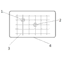
Fig. 1 is the structural representation of the utility model.
Embodiment
Below in conjunction with accompanying drawing the utility model is described in further detail:
As shown in Figure 1, the utility model is provided with the netted circuit 3 of ditching type at the dorsal part of base 4, in the netted circuit 3 of ditching type, slidably fan 2 is installed.Fan 2 is provided with two or three, and making it can be to a plurality of positions simultaneously to the row heat radiation.
The utility model user can slide to high temperature dot or high-temperature zone according to the notebook situation of specifically dispelling the heat voluntarily.Such as: the local position that is positioned at computer bottom holder hand place is overheated, so just can according to the netted wiring diagram of ditching type directly regulate slidably fan to heat radiation point below or near, dispel the heat targetedly.Just removed the waste of the radiating resource at other positions from.
The undeclared part that relates in the utility model is identical with prior art.
Claims (2)
1. a fan heat dissipation base slidably is characterized in that it comprises base (4), and said base (4) one sides are provided with the netted circuit of ditching type (3), and slidably fan (2) is installed in the netted circuit of ditching type (3).
2. slidably fan heat dissipation base according to claim 1 is characterized in that said fan (2) is provided with two or three.
Priority Applications (1)
| Application Number | Priority Date | Filing Date | Title |
|---|---|---|---|
| CN201120219528U CN202133950U (en) | 2011-06-27 | 2011-06-27 | Cooling base with slidable fan |
Applications Claiming Priority (1)
| Application Number | Priority Date | Filing Date | Title |
|---|---|---|---|
| CN201120219528U CN202133950U (en) | 2011-06-27 | 2011-06-27 | Cooling base with slidable fan |
Publications (1)
| Publication Number | Publication Date |
|---|---|
| CN202133950U true CN202133950U (en) | 2012-02-01 |
Family
ID=45522713
Family Applications (1)
| Application Number | Title | Priority Date | Filing Date |
|---|---|---|---|
| CN201120219528U Expired - Fee Related CN202133950U (en) | 2011-06-27 | 2011-06-27 | Cooling base with slidable fan |
Country Status (1)
| Country | Link |
|---|---|
| CN (1) | CN202133950U (en) |
Cited By (4)
| Publication number | Priority date | Publication date | Assignee | Title |
|---|---|---|---|---|
| CN102778938A (en) * | 2012-07-12 | 2012-11-14 | 成都依瑞克科技有限公司 | High-efficiency cooling device for computer cooling |
| CN102789293A (en) * | 2012-07-12 | 2012-11-21 | 成都依瑞克科技有限公司 | Computer-based efficient radiating device for multidirectional radiating |
| CN103257695A (en) * | 2013-05-03 | 2013-08-21 | 西南石油大学 | Laptop radiator |
| CN105116982A (en) * | 2015-09-30 | 2015-12-02 | 联想(北京)有限公司 | Heat dissipation stand and control method thereof |
-
2011
- 2011-06-27 CN CN201120219528U patent/CN202133950U/en not_active Expired - Fee Related
Cited By (4)
| Publication number | Priority date | Publication date | Assignee | Title |
|---|---|---|---|---|
| CN102778938A (en) * | 2012-07-12 | 2012-11-14 | 成都依瑞克科技有限公司 | High-efficiency cooling device for computer cooling |
| CN102789293A (en) * | 2012-07-12 | 2012-11-21 | 成都依瑞克科技有限公司 | Computer-based efficient radiating device for multidirectional radiating |
| CN103257695A (en) * | 2013-05-03 | 2013-08-21 | 西南石油大学 | Laptop radiator |
| CN105116982A (en) * | 2015-09-30 | 2015-12-02 | 联想(北京)有限公司 | Heat dissipation stand and control method thereof |
Similar Documents
| Publication | Publication Date | Title |
|---|---|---|
| CN202133950U (en) | Cooling base with slidable fan | |
| CN202230431U (en) | Laptop radiator with adjustable radiator fans | |
| CN204229336U (en) | A kind of computer cabinet of high heat radiation | |
| CN204576349U (en) | A kind of dismountable portable computer cooling stand | |
| CN202799528U (en) | Water cooling type electronic radiator | |
| CN203217461U (en) | Multifunctional computer radiating seat | |
| CN208110513U (en) | A kind of Multifunctional notebook radiator | |
| CN202404516U (en) | Heat dissipation base of notebook computer | |
| CN203250254U (en) | Notebook computer side face radiator with adjustable height | |
| CN205121461U (en) | Notebook computer heat radiation structure with adjustable | |
| CN203397290U (en) | Heat radiator for laptop | |
| CN204679899U (en) | A kind of Novel laptop keyboard | |
| CN203720769U (en) | Heat source separated cooling fin for computer | |
| CN201689377U (en) | Novel drawing type notebook computer heat radiation board | |
| CN202523769U (en) | LED radiator | |
| CN202902228U (en) | Heat sink device of semiconductor lighting fitting | |
| CN203784877U (en) | Heat dissipation structure | |
| CN203455767U (en) | Environmental-friendly and energy-saving computer host | |
| CN207503154U (en) | A kind of Novel laptop cooler | |
| CN207217589U (en) | A kind of electrothermal module radiator structure | |
| CN202331333U (en) | Notebook computer cooler | |
| CN205232002U (en) | Inside heat dissipation grillage of converter | |
| CN205334353U (en) | High -efficiency CPU heat dissipation sheet | |
| CN202636062U (en) | Laptop desk | |
| CN206036968U (en) | Light - emitting diode (LED) lamp radiator |
Legal Events
| Date | Code | Title | Description |
|---|---|---|---|
| C14 | Grant of patent or utility model | ||
| GR01 | Patent grant | ||
| C17 | Cessation of patent right | ||
| CF01 | Termination of patent right due to non-payment of annual fee |
Granted publication date: 20120201 Termination date: 20120627 |