CN202133361U - Go and no-go gauge - Google Patents
Go and no-go gauge Download PDFInfo
- Publication number
- CN202133361U CN202133361U CN201120130934U CN201120130934U CN202133361U CN 202133361 U CN202133361 U CN 202133361U CN 201120130934 U CN201120130934 U CN 201120130934U CN 201120130934 U CN201120130934 U CN 201120130934U CN 202133361 U CN202133361 U CN 202133361U
- Authority
- CN
- China
- Prior art keywords
- gage
- logical
- diameter
- utility
- aperture
- Prior art date
- Legal status (The legal status is an assumption and is not a legal conclusion. Google has not performed a legal analysis and makes no representation as to the accuracy of the status listed.)
- Expired - Fee Related
Links
Images
Landscapes
- Length-Measuring Instruments Using Mechanical Means (AREA)
Abstract
The utility model discloses a go and no-go gauge, comprising a gauge body (1), a working end of which is successively provided with a go end (2) and a non-go end (3) which are coaxial and located along the gauge body; the go end (2) is located on the working end, and the diameter of the go end (2) is equal to the allowed deviation lower limit of apertures of products to be detected; the diameter of the non-go end (3) is equal to the allowed deviation upper limit of the apertures of products to be detected. The go and no-go gauge of the utility model has the advantages of convenient operation and high efficiency in a process of detecting a mass of products.
Description
Technical field
The utility model relates to a kind of measurer, specifically is a kind of logical no-go gage.
Background technology
Logical no-go gage is a kind of of measurer, and large batch of product in actual production is measured very bothersome if take with metering measurer (like vernier caliper, graduated measurer such as clock gauge) one by one.We know that qualified product has a tolerance scope, and all qualified in this scope is so people just take logical no-go gage to measure.
At present, comparatively common logical no-go gage comprises a rule body, and an end of rule body is done not-go-end by the upper limit of product aperture permissible variation, and the other end of rule body is done the go side by the lower limit of product aperture permissible variation.During check,, explain that the product aperture is big if not-go-end can pass through the product aperture, defective, and can not heavily process; If the product aperture can not be passed through in the go side, explain that then the product aperture is little, also be defective, but can make it qualified through heavily processing.
Adopt the logical no-go gage of above structure, because go side and not-go-end lay respectively at the two ends of rule body, when the same aperture of check identical product; The two ends that need to lead to no-go gage are inserted respectively in the product aperture and could be accomplished work for inspection; That is to say that in checkout procedure logical no-go gage is wanted to insert in the product aperture for twice and could be accomplished work for inspection, this is for the check of typical products in mass production; Operate and be not easily to have influenced checkability to a certain extent.
The utility model content
The utility model technical matters to be solved is to provide a kind of when the check typical products in mass production, the logical no-go gage easy to operate, that efficient is high.
For solving the problems of the technologies described above; The logical no-go gage that the utility model provides; It comprises the rule body, and to being provided with coaxial go side, not-go-end successively, said go side is positioned at the end of working end along the rule axon in the working end of said rule body; The diameter of said go side equates that with the lower limit of examined product aperture permissible variation the diameter of said not-go-end equates with the upper limit of examined product aperture permissible variation.
Be provided with annular ramp pan between said go side and the not-go-end.
After adopting above structure, the logical no-go gage of the utility model compared with prior art has the following advantages: because the working end of rule body is along advising axon to being provided with coaxial go side, not-go-end successively; And the go side is positioned at the end of working end, and the diameter of go side equates that with the lower limit of examined product aperture permissible variation the diameter of not-go-end equates with the upper limit of examined product aperture permissible variation; Like this, when the same aperture of check identical product, go side, the not-go-end of logical no-go gage working end are inserted in the examined product aperture successively; Just can check out the aperture whether to meet the demands successively; That is to say that in checkout procedure logical no-go gage is as long as insert in the product aperture and once just can accomplish work for inspection, during for the check typical products in mass production; Operating, it is a lot of to make things convenient for, and has also improved checkability simultaneously.
As improvement, be provided with annular ramp pan between said go side and the not-go-end, be convenient to the transition processing of go side and not-go-end.
Description of drawings
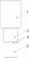
Accompanying drawing 1 is the structural representation of the logical no-go gage of the utility model.
Shown in the figure: 1, rule body, 2, the go side, 3, not-go-end, 4, annular ramp pan.
Embodiment
Below in conjunction with accompanying drawing and embodiment the utility model is done further detailed explanation.
Shown in accompanying drawing, the logical no-go gage of the utility model, it comprises rule body 1, to being provided with coaxial go side 2, not-go-end 3 successively, said go side 2 is positioned at the end of working end along the rule axon in the working end of said rule body 1.The diameter of said go side 2 equates that with the lower limit of examined product aperture permissible variation the diameter of said not-go-end 3 equates with the upper limit of examined product aperture permissible variation.
When using the logical no-go gage of the utility model, the examined product mean level is placed, and the working end of logical no-go gage then is inserted in the aperture of examined product down, and this moment, go side 2, not-go-end 3 were tested to the product aperture successively.
As the improvement of present embodiment, be provided with annular ramp pan 4 between said go side 2 and the not-go-end 3.
Claims (2)
1. logical no-go gage; It comprises rule body (1); It is characterized in that: the working end of said rule body (1) is along advising axon to being provided with coaxial go side (2), not-go-end (3) successively; Said go side (2) is positioned at the end of working end, and the diameter of said go side (2) equates that with the lower limit of examined product aperture permissible variation the diameter of said not-go-end (3) equates with the upper limit of examined product aperture permissible variation.
2. logical no-go gage according to claim 1 is characterized in that: be provided with annular ramp pan (4) between said go side (2) and the not-go-end (3).
Priority Applications (1)
| Application Number | Priority Date | Filing Date | Title |
|---|---|---|---|
| CN201120130934U CN202133361U (en) | 2011-04-28 | 2011-04-28 | Go and no-go gauge |
Applications Claiming Priority (1)
| Application Number | Priority Date | Filing Date | Title |
|---|---|---|---|
| CN201120130934U CN202133361U (en) | 2011-04-28 | 2011-04-28 | Go and no-go gauge |
Publications (1)
| Publication Number | Publication Date |
|---|---|
| CN202133361U true CN202133361U (en) | 2012-02-01 |
Family
ID=45522127
Family Applications (1)
| Application Number | Title | Priority Date | Filing Date |
|---|---|---|---|
| CN201120130934U Expired - Fee Related CN202133361U (en) | 2011-04-28 | 2011-04-28 | Go and no-go gauge |
Country Status (1)
| Country | Link |
|---|---|
| CN (1) | CN202133361U (en) |
Cited By (5)
| Publication number | Priority date | Publication date | Assignee | Title |
|---|---|---|---|---|
| CN103234426A (en) * | 2013-04-10 | 2013-08-07 | 黄石市科兴机电科技有限公司 | Automatic through-hole diameter detecting device and automatic through-hole diameter detecting method |
| CN103411500A (en) * | 2013-07-25 | 2013-11-27 | 苏州苏明装饰股份有限公司 | Back bolt hole detecting tool |
| CN105300217A (en) * | 2015-11-25 | 2016-02-03 | 重庆万事通机械制造有限公司 | Disc hub core blank detection tool |
| CN105333792A (en) * | 2015-11-20 | 2016-02-17 | 重庆万事通机械制造有限公司 | Dual-purpose hole-detection tool for automotive parts |
| CN105627877A (en) * | 2015-12-30 | 2016-06-01 | 陕西国防工业职业技术学院 | Go-no go gauge |
-
2011
- 2011-04-28 CN CN201120130934U patent/CN202133361U/en not_active Expired - Fee Related
Cited By (8)
| Publication number | Priority date | Publication date | Assignee | Title |
|---|---|---|---|---|
| CN103234426A (en) * | 2013-04-10 | 2013-08-07 | 黄石市科兴机电科技有限公司 | Automatic through-hole diameter detecting device and automatic through-hole diameter detecting method |
| CN103234426B (en) * | 2013-04-10 | 2015-11-18 | 黄石市科兴机电科技有限公司 | The automatic detection device of through-hole diameter |
| CN103411500A (en) * | 2013-07-25 | 2013-11-27 | 苏州苏明装饰股份有限公司 | Back bolt hole detecting tool |
| CN103411500B (en) * | 2013-07-25 | 2016-01-20 | 苏州苏明装饰股份有限公司 | Back of the body keyhole testing tool |
| CN105333792A (en) * | 2015-11-20 | 2016-02-17 | 重庆万事通机械制造有限公司 | Dual-purpose hole-detection tool for automotive parts |
| CN105300217A (en) * | 2015-11-25 | 2016-02-03 | 重庆万事通机械制造有限公司 | Disc hub core blank detection tool |
| CN105627877A (en) * | 2015-12-30 | 2016-06-01 | 陕西国防工业职业技术学院 | Go-no go gauge |
| CN105627877B (en) * | 2015-12-30 | 2018-08-24 | 陕西国防工业职业技术学院 | Go-no go gauge |
Similar Documents
| Publication | Publication Date | Title |
|---|---|---|
| CN202133361U (en) | Go and no-go gauge | |
| CN202361926U (en) | Integrated ring gauge | |
| CN203501927U (en) | Go-no go gauge having depth detection function | |
| CN205002690U (en) | Coarse pitch thread profile gauge rule | |
| CN202648597U (en) | Coupling sleeve step surface to stepped hole surface depth measuring gauge | |
| CN207763625U (en) | A kind of sawtooth pattern king-bolt accuracy of thread comprehensive check tool | |
| CN204154296U (en) | A kind of structure of comprehensive check tool of turbine case | |
| CN202562398U (en) | Portable detection gauge | |
| CN204902694U (en) | Aperture measuring device | |
| CN202255174U (en) | Go/no go gauge for detecting car door frame gap | |
| CN202747970U (en) | H-shaped height go-no go gauge | |
| CN202092530U (en) | Examining sample plate for outer arc | |
| CN205262377U (en) | Novel a profile tolerance detects for part curved surface device | |
| CN205279963U (en) | Measuring tool | |
| CN202195789U (en) | One-way go/no go gauge | |
| CN204831123U (en) | Many function combination of height gage chaining pin | |
| CN103512458A (en) | Device for testing taper cylinder sleeve | |
| CN204396529U (en) | For reflecting the latch cubing of small size stamping parts punching quality | |
| CN204043545U (en) | A kind of go-no go gauge with step and bearing pin | |
| CN203719577U (en) | Upper center pan outer cone measuring gauge | |
| CN204202526U (en) | Securing member foreign side rapid detection tool | |
| CN205426014U (en) | Utensil is examined to screw hole | |
| CN203364715U (en) | A thickness no-go go gauge | |
| CN203744905U (en) | Direct-reading straightness measuring device | |
| CN105004473B (en) | Counterweight loading equipemtn |
Legal Events
| Date | Code | Title | Description |
|---|---|---|---|
| C14 | Grant of patent or utility model | ||
| GR01 | Patent grant | ||
| C17 | Cessation of patent right | ||
| CF01 | Termination of patent right due to non-payment of annual fee |
Granted publication date: 20120201 Termination date: 20140428 |