CN202103337U - Transformer box with folding edge structure box cover - Google Patents
Transformer box with folding edge structure box cover Download PDFInfo
- Publication number
- CN202103337U CN202103337U CN2011201541393U CN201120154139U CN202103337U CN 202103337 U CN202103337 U CN 202103337U CN 2011201541393 U CN2011201541393 U CN 2011201541393U CN 201120154139 U CN201120154139 U CN 201120154139U CN 202103337 U CN202103337 U CN 202103337U
- Authority
- CN
- China
- Prior art keywords
- transformer
- box cover
- folding edges
- box
- case lid
- Prior art date
- Legal status (The legal status is an assumption and is not a legal conclusion. Google has not performed a legal analysis and makes no representation as to the accuracy of the status listed.)
- Expired - Fee Related
Links
Images
Abstract
The utility model discloses a transformer box which comprises a transformer box body and a box cover. A box eave is arranged at the top part of the transformer box body; the edge of the box cover is provided with downward folding edges; and a notch is arranged between two adjacent folding edges. As the edge of the box cover is provided with the downward folding edges, and rain water on the transformer box cover can flow downwards along the folding edges without entering into a sealing part in a rainy day so as to avoid affecting sealing performance due to penetration of the rain water. The notch is arranged between the two adjacent folding edges so that the box cover is easy to manufacture, and the manufacturing cost is low. In addition, due to the blocking of the folding edges, the problem of aging a sealing rubber strip caused by ultraviolet irradiation to affect the sealing performance is solved; thereby ensuring the safe operation of a power transformer.
Description
Technical field
The utility model belongs to the power transmission and transforming equipment technical field, is specifically related to a kind of transformer tank with flanging structure case lid.
Background technology
At present, most of power transformer case case is along use flat plate usually, and case lid also adopts plate armature.Because case lid is plate armature, case cover and case along between have the gap, rainwater easily along case lid from case lid with the case edge between the gap enter into seals at, cause easily and seep water and influence performance of products; In addition, the sealing joint strip that exposes is subject to ultraviolet irradiation and wears out, and influences its sealing property.
The utility model content
The purpose of the utility model is to solve the above-mentioned technical problem that exists in the prior art, and a kind of transformer tank is provided.
For realizing above-mentioned purpose, the technical scheme that the utility model adopts is following:
The transformer tank of the utility model comprises transformer-cabinet and case lid, and the transformer-cabinet top is provided with the case edge, and the edge of case lid is provided with downward flanging, is provided with breach between adjacent two flangings.
Angle between flanging and the case lid less than 90 the degree, between flanging and the case lid end face by arc transition.
Because the utility model is provided with downward flanging at the edge of case lid, when raining, the rainwater that transformer tank covers can be dirty along flanging, can not get into seals at, and having avoided influences sealing property because of rainwater infiltrates.Be provided with breach between adjacent two flangings, being easy to case lid like this must process, and it is low to make the ability cost.In addition, because flanging blocks, solved the problem of sealing joint strip because of ultraviolet irradiation burn-in effects sealing property.Thereby guaranteed the safe operation of power transformer.
Description of drawings
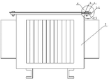
Fig. 1 is the structural representation of the utility model.
Fig. 2 is an A part partial enlarged drawing among Fig. 1.
Embodiment
The transformer tank of the utility model comprises transformer-cabinet 2 and case lid 1, and transformer-cabinet 2 tops are provided with case along 2-1, and the edge of case lid 1 is provided with downward flanging 1-1, is provided with breach between adjacent two flangings.
Angle between flanging 1-1 and the case lid 1 less than 90 the degree, between flanging 1-1 and case lid 1 end face by arc transition.
In the utility model when assembling,, the case that case lid 1 is covered the power transformer casing of having placed sealing joint strip 3 is along on the 2-1, connects fixingly then through fastening bolt 4, and the turnup structure on the case lid plays the covering effect to sealing joint strip.
Claims (2)
1. a transformer tank comprises transformer-cabinet and case lid, and the transformer-cabinet top is provided with the case edge, it is characterized in that: the edge of case lid is provided with downward flanging, is provided with breach between adjacent two flangings.
2. the transformer tank with flanging structure case lid according to claim 1 is characterized in that: the angle between flanging and the case lid less than 90 the degree, between flanging and the case lid end face by arc transition.
Priority Applications (1)
| Application Number | Priority Date | Filing Date | Title |
|---|---|---|---|
| CN2011201541393U CN202103337U (en) | 2011-05-16 | 2011-05-16 | Transformer box with folding edge structure box cover |
Applications Claiming Priority (1)
| Application Number | Priority Date | Filing Date | Title |
|---|---|---|---|
| CN2011201541393U CN202103337U (en) | 2011-05-16 | 2011-05-16 | Transformer box with folding edge structure box cover |
Publications (1)
| Publication Number | Publication Date |
|---|---|
| CN202103337U true CN202103337U (en) | 2012-01-04 |
Family
ID=45389334
Family Applications (1)
| Application Number | Title | Priority Date | Filing Date |
|---|---|---|---|
| CN2011201541393U Expired - Fee Related CN202103337U (en) | 2011-05-16 | 2011-05-16 | Transformer box with folding edge structure box cover |
Country Status (1)
| Country | Link |
|---|---|
| CN (1) | CN202103337U (en) |
Cited By (1)
| Publication number | Priority date | Publication date | Assignee | Title |
|---|---|---|---|---|
| CN102938293A (en) * | 2012-11-23 | 2013-02-20 | 山东东政变压器有限公司 | Small and medium-size transformer oil tank |
-
2011
- 2011-05-16 CN CN2011201541393U patent/CN202103337U/en not_active Expired - Fee Related
Cited By (1)
| Publication number | Priority date | Publication date | Assignee | Title |
|---|---|---|---|---|
| CN102938293A (en) * | 2012-11-23 | 2013-02-20 | 山东东政变压器有限公司 | Small and medium-size transformer oil tank |
Similar Documents
| Publication | Publication Date | Title |
|---|---|---|
| CN202103337U (en) | Transformer box with folding edge structure box cover | |
| CN201018203Y (en) | Double-layer seal structure of box type transformer station door | |
| CN201853956U (en) | Rainproof structure for top cover of box-type substation | |
| CN203481650U (en) | Rainwater leakage preventing power distribution box | |
| CN205543755U (en) | Caping structure of family dominant exterior cabinet | |
| CN203278167U (en) | Novel reinforced insulating seal cap | |
| CN202103338U (en) | Transformer box with box cover provided with folded edges | |
| CN202268279U (en) | Direct-current grounding prevention device for operating auxiliary switch of isolating switch | |
| CN201540800U (en) | Fuel tank sealing device of transformer | |
| CN205355089U (en) | Battery package seal structure | |
| CN201818962U (en) | Muting cover for electric generating set | |
| CN202990261U (en) | Rainproof roof of substation | |
| CN202103339U (en) | Transformer box provided with baffle plate structure with folded eaves | |
| CN205230731U (en) | Fuel tank cap of transformer | |
| CN204392701U (en) | A kind of controller cover plate | |
| CN203289789U (en) | Outdoor detection control box | |
| CN204646024U (en) | A kind of rolling door sealing device | |
| CN202487333U (en) | Transformer tank cover of omnisealed corrugated oil tank | |
| CN203774642U (en) | Prefabricated case of transformer station | |
| CN202294873U (en) | Anti-loosening device of manual cover of switch machine | |
| CN202945945U (en) | Fixed push-pull integrated plastics-steel door-window | |
| CN202651647U (en) | Outdoor double-layer water-insulating and waterproof power distribution box | |
| CN202856508U (en) | Motor with waterproof and dustproof structure | |
| CN201598941U (en) | Profile material arranged at internal lower part of single glass | |
| CN202196641U (en) | Tank cover for oil tank of transformer |
Legal Events
| Date | Code | Title | Description |
|---|---|---|---|
| C14 | Grant of patent or utility model | ||
| GR01 | Patent grant | ||
| CF01 | Termination of patent right due to non-payment of annual fee |
Granted publication date: 20120104 Termination date: 20150516 |
|
| EXPY | Termination of patent right or utility model |