CN202095212U - Hollow machine body of electric appliance - Google Patents
Hollow machine body of electric appliance Download PDFInfo
- Publication number
- CN202095212U CN202095212U CN2011201743624U CN201120174362U CN202095212U CN 202095212 U CN202095212 U CN 202095212U CN 2011201743624 U CN2011201743624 U CN 2011201743624U CN 201120174362 U CN201120174362 U CN 201120174362U CN 202095212 U CN202095212 U CN 202095212U
- Authority
- CN
- China
- Prior art keywords
- support platform
- section bar
- substrate
- hollow
- connector
- Prior art date
- Legal status (The legal status is an assumption and is not a legal conclusion. Google has not performed a legal analysis and makes no representation as to the accuracy of the status listed.)
- Expired - Fee Related
Links
Images


Abstract
A hollow machine body of an electric appliance is formed by a bent linear profile with two ends fixedly connected. The profile comprises a substrate perpendicular to the horizontal plane, a hollow upper supporting platform positioned at the lower opening of one side of the substrate, a hollow lower supporting platform positioned at the upper opening of one side of the substrate, and a gap is formed between the upper supporting platform and the lower supporting platform; a plurality of notches formed on the profile communicate the upper supporting platform and the lower supporting platform in a penetrating manner, the bisectors of the corners of the notches are perpendicular to the substrate; the substrate bends at the notches, the two end surfaces of the upper supporting platform at the notches are jointed, and the two ends surfaces of the lower supporting platform at the notches are also jointed; and the two ends of the profile are fixedly connected with a fixing part. By adopting the structure, no gap is formed at the joint angles of frames of a base, the surface is smooth and clean, and the safety hazards are eliminated.
Description
Technical field
The utility model relates to the device that a kind of electrical equipment is used, especially a kind of body of electrical equipment.
Background technology
Present prior art, a kind of hollow body of electrical equipment comprises four frames, four frames are fixedly connected to be square frame shape.Another kind is that four frames connect by the dihedral connector.Existing problems are: existing problems are: periphery has seam, and rough surface has potential safety hazard when wiping examination, damages hand easily.
The utility model content
The purpose of this utility model is: a kind of body of electrical equipment hollow is provided, and it does not only have seam in the intersection of frame, and has eliminated potential safety hazard.
The utility model is achieved in that a kind of body of electrical equipment hollow, and it is by a rectilinear section bar bending, and two ends are fixedly connected makes; Section bar comprises substrate perpendicular to horizontal plane, be positioned at substrate one side under shed hollow the upper support platform and be positioned at the lower support platform of hollow of the upper shed of substrate one side, gapped between upper support platform and the lower support platform; Have some otch to connect upper and lower brace table on section bar, the bisector of angle of otch is perpendicular to substrate;
The substrate bending of incision, two end faces of incision upper support platform are fitted, and two end faces of the lower support platform of incision are fitted; Fixedly connected with a fixture in the section bar two ends.
The body of described a kind of electrical equipment hollow, its special character is: described connector comprises base plate, be arranged on the boss on the base plate and be positioned at the pin plate of boss upper/lower terminal both sides;
Connector is arranged between the both ends of section bar, and pin plate inserts in upper support platform and the lower support platform, and a screw is fixedlyed connected pin plate with upper and lower brace table, and the both sides of base plate cooperate with the base board end surface of section bar.
The body of described a kind of electrical equipment hollow, what it was special is: described connector is plate shaped, and two end faces of section bar are fitted, and connector is plugged, in the lower support platform, and a screw is fixedlyed connected connector with upper and lower brace table.
A kind of body of electrical equipment hollow, it comprises at least two rectilinear section bars, described section bar comprises substrate perpendicular to horizontal plane, be positioned at a basic side under shed hollow the upper support platform and be positioned at the lower support platform of hollow of the upper shed of substrate one side, gapped between upper support platform and the lower support platform; Have some otch to connect upper and lower brace table on section bar, the bisector of angle of otch is perpendicular to substrate;
The substrate bending of incision, two end faces of incision upper support platform are fitted, and two end faces of the lower support platform of incision are fitted;
Adjacent two section bars are fixedly connected by connector.
The hollow base of described a kind of electrical equipment, its special character is: described connector comprises base plate, be arranged on the boss on the base plate and be positioned at the pin plate of boss upper/lower terminal both sides;
Connector is arranged between the both ends of adjacent two section bars, and pin plate inserts in upper support platform and the lower support platform, and a screw is fixedlyed connected pin plate with upper and lower brace table, and the both sides of base plate cooperate with the base board end surface of section bar.
The body of described a kind of electrical equipment hollow, its special character is: described connector is plate shaped, and two end faces of adjacent two section bars are fitted, and connector is plugged, in the lower support platform, and a screw is fixedlyed connected connector with upper and lower brace table.
The body of a kind of electrical equipment hollow of the utility model, owing to adopt such structure, the angle of cut place of each frame of base is seamless, any surface finish has been eliminated potential safety hazard.
Description of drawings
Fig. 1 is a front view of the present utility model.
Fig. 2 is the enlarged drawing of Fig. 1.
Fig. 3 is the sectional drawing of the utility model section bar.
Fig. 4 is the front view of the utility model section bar.
Fig. 5 is the front view of the utility model connector.
Fig. 6 is the left view of the utility model connector.
Fig. 7 is the front view of second kind of execution mode of the utility model.
Embodiment
Below in conjunction with accompanying drawing the utility model is further described.
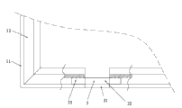
As Fig. 1, Fig. 2, Fig. 3, shown in Figure 4, a kind of body of electrical equipment hollow, it comprises a rectilinear section bar 1, section bar 1 comprises substrate 11 perpendicular to horizontal plane, be positioned at substrate one side under shed hollow upper support platform 12 and be positioned at the lower support platform 13 of hollow of the upper shed of substrate one side, between upper support platform 12 and the lower support platform 13 groove is arranged; Have four otch 2 to connect upper and lower brace table 12,13 on section bar 1, the bisector of angle of otch 2 is perpendicular to substrate 11; The angle of otch is 90 degree, can make square body like this.When the otch angle is 60 when spending, can make hexagonal body.
The substrate bending at otch 2 places, 12 two end faces of otch 2 place's upper support platforms are fitted, and two end faces of the lower support platform 13 at otch 2 places are fitted; Fixedly connected with a fixture 3 in section bar 1 two ends.
Described connector 3 comprises base plate 31, be arranged on the boss 32 on the base plate 31 and be positioned at the pin plate 33 of boss 32 upper/lower terminal both sides;
The utility model in use, upper support platform 12 is placed the panel of electrical equipment, on the lower support platform bottom plate is set.
The purpose of this utility model also can realize like this: described connector 3 is plate shaped, and two end faces of section bar 1 are fitted, and connector 3 is plugged, in the lower support platform 12,13, and a screw is fixedlyed connected connector 3 with upper and lower brace table 12,13.
As shown in Figure 7, a kind of body of electrical equipment hollow, it comprises the right frame 4 of the left opening that 2, two section bars 2 of two rectilinear section bars are made respectively, the left frame 5 of a right opening,
Above-described only is preferential execution mode of the present utility model.Should be pointed out that for the person of ordinary skill of the art under the situation that does not break away from the utility model principle, can also make some improvement and modification, this also is considered as protection range of the present utility model.
Claims (6)
1. the body of an electrical equipment hollow, it is by a rectilinear section bar bending, and two ends are fixedly connected makes; Section bar comprises substrate perpendicular to horizontal plane, be positioned at substrate one side under shed hollow the upper support platform and be positioned at the lower support platform of hollow of the upper shed of substrate one side, gapped between upper support platform and the lower support platform; Have some otch to connect upper and lower brace table on section bar, the bisector of angle of otch is perpendicular to substrate;
The substrate bending of incision, two end faces of incision upper support platform are fitted, and two end faces of the lower support platform of incision are fitted; Fixedly connected with a fixture in the section bar two ends.
2. the body of a kind of electrical equipment hollow according to claim 1 is characterized in that: described connector comprises base plate, be arranged on the boss on the base plate and be positioned at the pin plate of boss upper/lower terminal both sides;
Connector is arranged between the both ends of section bar, and pin plate inserts in upper support platform and the lower support platform, and a screw is fixedlyed connected pin plate with upper and lower brace table, and the both sides of base plate cooperate with the base board end surface of section bar.
3. the body of a kind of electrical equipment hollow according to claim 1 is characterized in that: described connector is plate shaped, and two end faces of section bar are fitted, and connector is plugged, in the lower support platform, and a screw is fixedlyed connected connector with upper and lower brace table.
4. the body of an electrical equipment hollow, it comprises at least two rectilinear section bars, described section bar comprises substrate perpendicular to horizontal plane, be positioned at a basic side under shed hollow the upper support platform and be positioned at the lower support platform of hollow of the upper shed of substrate one side, gapped between upper support platform and the lower support platform; Have some otch to connect upper and lower brace table on section bar, the bisector of angle of otch is perpendicular to substrate;
The substrate bending of incision, two end faces of incision upper support platform are fitted, and two end faces of the lower support platform of incision are fitted;
Adjacent two section bars are fixedly connected by connector.
5. the hollow base of a kind of electrical equipment according to claim 4 is characterized in that: described connector comprises base plate, be arranged on the boss on the base plate and be positioned at the pin plate of boss upper/lower terminal both sides;
Connector is arranged between the both ends of section bar, and pin plate inserts in upper support platform and the lower support platform, and a screw is fixedlyed connected pin plate with upper and lower brace table, and the both sides of base plate cooperate with the base board end surface of section bar.
6. the body of a kind of electrical equipment hollow according to claim 4 is characterized in that: described connector is plate shaped, and two end faces of section bar are fitted, and connector is plugged, in the lower support platform, and a screw is fixedlyed connected connector with upper and lower brace table.
Priority Applications (1)
| Application Number | Priority Date | Filing Date | Title |
|---|---|---|---|
| CN2011201743624U CN202095212U (en) | 2011-05-27 | 2011-05-27 | Hollow machine body of electric appliance |
Applications Claiming Priority (1)
| Application Number | Priority Date | Filing Date | Title |
|---|---|---|---|
| CN2011201743624U CN202095212U (en) | 2011-05-27 | 2011-05-27 | Hollow machine body of electric appliance |
Publications (1)
| Publication Number | Publication Date |
|---|---|
| CN202095212U true CN202095212U (en) | 2011-12-28 |
Family
ID=45370249
Family Applications (1)
| Application Number | Title | Priority Date | Filing Date |
|---|---|---|---|
| CN2011201743624U Expired - Fee Related CN202095212U (en) | 2011-05-27 | 2011-05-27 | Hollow machine body of electric appliance |
Country Status (1)
| Country | Link |
|---|---|
| CN (1) | CN202095212U (en) |
Cited By (1)
| Publication number | Priority date | Publication date | Assignee | Title |
|---|---|---|---|---|
| CN102256456A (en) * | 2011-05-27 | 2011-11-23 | 谢贯芝 | Hollow machine body of electrical appliance and manufacturing method thereof |
-
2011
- 2011-05-27 CN CN2011201743624U patent/CN202095212U/en not_active Expired - Fee Related
Cited By (1)
| Publication number | Priority date | Publication date | Assignee | Title |
|---|---|---|---|---|
| CN102256456A (en) * | 2011-05-27 | 2011-11-23 | 谢贯芝 | Hollow machine body of electrical appliance and manufacturing method thereof |
Similar Documents
| Publication | Publication Date | Title |
|---|---|---|
| CN103220892B (en) | A kind of electrical control rack based on aluminium section bar | |
| CN202095212U (en) | Hollow machine body of electric appliance | |
| CN203488969U (en) | Multifunctional rapid combination section bar | |
| CN204617412U (en) | A kind of fast assembling desk | |
| CN102256456A (en) | Hollow machine body of electrical appliance and manufacturing method thereof | |
| CN204105521U (en) | Showing stand | |
| CN202427865U (en) | Electronic element pin bending device | |
| CN105350742B (en) | A kind of self-heating floor | |
| CN205276776U (en) | Self -heating floor | |
| CN205350831U (en) | Instruct right angle bending for mounting bracket in fact | |
| CN204754444U (en) | Clamp plate of protection rail stand | |
| CN203603268U (en) | Connecting piece for stand column and transverse rod | |
| CN204551887U (en) | A kind of lightweight section structure spandrel girder | |
| CN205203754U (en) | Prevent glass contact and insert frame | |
| CN203448999U (en) | Frame section bar | |
| CN204839510U (en) | Human composition analysis appearance | |
| CN203943293U (en) | A kind of desk stand | |
| CN201717143U (en) | Wall switch | |
| CN207660202U (en) | Handrail guardrail support overlap-connected components | |
| CN207794580U (en) | Spliced type device with pedal | |
| CN204483426U (en) | A kind of metal platform pin, platform foot rest connector, platform foot rest and conference table | |
| CN103046687A (en) | Partitioning plate | |
| CN206302124U (en) | A kind of bar top porcelain vase frame | |
| CN204732996U (en) | A kind of motor support frame | |
| CN104895403A (en) | Protective fence stand column press plate |
Legal Events
| Date | Code | Title | Description |
|---|---|---|---|
| C14 | Grant of patent or utility model | ||
| GR01 | Patent grant | ||
| C17 | Cessation of patent right | ||
| CF01 | Termination of patent right due to non-payment of annual fee |
Granted publication date: 20111228 Termination date: 20140527 |