CN202094551U - Wire slot adaptor - Google Patents
Wire slot adaptor Download PDFInfo
- Publication number
- CN202094551U CN202094551U CN201120234184XU CN201120234184U CN202094551U CN 202094551 U CN202094551 U CN 202094551U CN 201120234184X U CN201120234184X U CN 201120234184XU CN 201120234184 U CN201120234184 U CN 201120234184U CN 202094551 U CN202094551 U CN 202094551U
- Authority
- CN
- China
- Prior art keywords
- wire casing
- accessory
- wire slot
- connector
- adaptor
- Prior art date
- Legal status (The legal status is an assumption and is not a legal conclusion. Google has not performed a legal analysis and makes no representation as to the accuracy of the status listed.)
- Expired - Fee Related
Links
Images


Landscapes
- Installation Of Indoor Wiring (AREA)
Abstract
The utility model discloses a wire slot adaptor, comprising a wire slot connector and a fitting fixing member; one end of the wire slot connector is a wire slot connecting port and connected with the wire slot, and the other end is connected with the fitting fixing member; the fitting fixing member comprises a sheet structure; the centre of the sheet structure is provided with a circular hole; a connecting structure connected with the wire slot connector is arranged on the circumference of the circular hole. The utility model solves the problem of adapting the wire slot and the fitting, so that the wire slot and the fitting are fixedly connected better and the potential safety hazard is avoided effectively; and the wire slot adaptor has simple structure and is convenient to operate.
Description
Technical field
The utility model relates to the wire rod installing area, relates in particular to a kind of wire casing adaptor.
Background technology
Wire casing (as conduit) all is to use very general product during the architectural electricity circuit is installed with accessory (as switch enclosure), and wire casing is used for the installation of electric wire rod and fixes, and accessory is used to install electric components such as switch, socket.
Screwed pipe joint is mainly adopted in being connected between present wire casing and the accessory, and pipe joint divides two parts, and a part is placed in the accessory box, and another part is outside box, and two parts are by being threaded.Since cumbersome when being threaded in actual installation, screwed pipe joint generally only when the concealed installation switch enclosure, just adopted, and most of bright dress is not adopt pipe joint.
There is not corresponding connector between wire casing and the accessory at present, so when actual installation, do not have accessory to be connected between wire casing and the accessory.Leave the slit between wire casing and the accessory, advance foreign material easily, neither attractive in appearance, easily stay potential safety hazard again.
The utility model content
The utility model has overcome deficiency of the prior art, and a kind of wire casing adaptor that is used to connect between wire casing and the accessory is provided, and wire casing and accessory closely can be linked together.
In order to realize above-mentioned purpose, adopt following technical scheme:
A kind of wire casing adaptor, comprise wire casing connector and accessory fixture, described wire casing connector one end is the wire casing connector, be connected with wire casing, the other end is connected with the accessory fixture, described accessory fixture comprises laminated structure, and the laminated structure center is provided with circular hole, and the circular hole circumference is provided with and wire casing connector connection structure connecting.The wire casing connector of wire casing connector is connected with wire casing, direct socket joint, and the accessory fixture is used for accessory and wire casing are connected and fixed.Accessory is provided with punching, and the syndeton of accessory fixture is passed punching from accessory inside, is connected with the wire casing connector of accessory outside, and laminated structure is stuck in the accessory.By being connected of wire casing connector and accessory fixture, realize the switching from the wire casing to the accessory.
Syndeton described in the utility model is a buckle, and described wire casing connector is provided with draw-in groove, and the draw-in groove limit is provided with the breach that passes through for buckle, and the wire casing connector is connected with the formation that is clasped by draw-in groove with the accessory fixture.By entering draw-in groove, rotation accessory fixture makes buckle leave breach to buckle, is locked in the draw-in groove from breach.Adopt the syndeton of buckle and draw-in groove, simple in structure, be easy for installation and removal.As preferably, described buckle is three, is evenly distributed on the circumference of circular hole.Three buckles form three-legged structure, and three-legged structure is the most stable firm structure, can make connection more reliable.
In the such scheme, described laminated structure is a polygonized structure.Polygonized structure is convenient to directly use manual manipulation, and installing/dismounting is more convenient.Described laminated structure is a hexagon, can cooperate with staff better, and staff is better exerted oneself.
Compared with prior art, the utility model has solved the switching problem of wire casing and accessory, and wire casing and accessory can be connected and fixed better, has avoided potential safety hazard effectively, and simple in structure, is convenient to operation.
Description of drawings
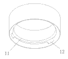
Fig. 1 is a user mode cutaway view of the present utility model;
Fig. 2 is a wire casing connector schematic diagram;
Fig. 3 is an accessory fixture schematic diagram.
Embodiment
The utility model will be further described below in conjunction with accompanying drawing.
User mode of the present utility model as shown in Figure 1, this wire casing adaptor comprises wire casing connector 1 and accessory fixture 2, is used for the switching between wire casing and the accessory.Accessory 3 is provided with punching, and accessory fixture 2 is connected with wire casing connector 1 one ends after stretching out punching from accessory 3 inside, and accessory 3 is clipped in the middle of the adaptor.The other end of wire casing connector 1 can produce the difformity structure, is used to connect the socket joint wire casing.
The structure of wire casing connector as shown in Figure 2.The end that wire casing connector 1 is connected with accessory fixture 2 is provided with draw-in groove 11, and the draw-in groove limit evenly is provided with 3 breach 12, and the other end is circular wire casing bell and spigot, can with direct socket joint such as conduit.The structure of accessory fixture as shown in Figure 3.The laminated structure 21 of accessory fixture 2 is a hexagon, and the centre has circular hole 22, evenly is provided with three buckles 23 on circular hole 22 circumference.Breach 12 is bigger slightly than buckle 23, and buckle 23 can enter draw-in groove by breach 12.
During installation, earlier the one side that is connected with wire casing at accessory 3 is stamped punching, is used to connect adaptor and wire rod such as electric wire is passed through.The laminated structure 21 of accessory fixture 2 is stuck in accessory inside, and buckle 23 passes from punching, and the breach 12 by wire casing connector 1 enters draw-in groove 11, and rotational lock, finishes the installation of adaptor.The other end of wire casing connector 1 and wire casing can be connected by modes such as direct socket joint or screw thread are fixing, are fixed to the first-class place of wall afterwards again, finish the whole erection process.
Claims (5)
1. wire casing adaptor, it is characterized in that, comprise wire casing connector and accessory fixture, described wire casing connector one end is the wire casing connector, be connected with wire casing, the other end is connected with the accessory fixture, and described accessory fixture comprises laminated structure, the laminated structure center is provided with circular hole, and the circular hole circumference is provided with and wire casing connector connection structure connecting.
2. wire casing adaptor according to claim 1, it is characterized in that described syndeton is a buckle, described wire casing connector is provided with draw-in groove, the draw-in groove limit is provided with the breach that passes through for buckle, and the wire casing connector is connected with the formation that is clasped by draw-in groove with the accessory fixture.
3. wire casing adaptor according to claim 2 is characterized in that described buckle is three, is evenly distributed on the circumference of circular hole.
4. according to each described wire casing adaptor among the claim 1-3, it is characterized in that described laminated structure is a polygonized structure.
5. wire casing adaptor according to claim 4 is characterized in that, described laminated structure is a hexagon.
Priority Applications (1)
| Application Number | Priority Date | Filing Date | Title |
|---|---|---|---|
| CN201120234184XU CN202094551U (en) | 2011-07-05 | 2011-07-05 | Wire slot adaptor |
Applications Claiming Priority (1)
| Application Number | Priority Date | Filing Date | Title |
|---|---|---|---|
| CN201120234184XU CN202094551U (en) | 2011-07-05 | 2011-07-05 | Wire slot adaptor |
Publications (1)
| Publication Number | Publication Date |
|---|---|
| CN202094551U true CN202094551U (en) | 2011-12-28 |
Family
ID=45369594
Family Applications (1)
| Application Number | Title | Priority Date | Filing Date |
|---|---|---|---|
| CN201120234184XU Expired - Fee Related CN202094551U (en) | 2011-07-05 | 2011-07-05 | Wire slot adaptor |
Country Status (1)
| Country | Link |
|---|---|
| CN (1) | CN202094551U (en) |
Cited By (1)
| Publication number | Priority date | Publication date | Assignee | Title |
|---|---|---|---|---|
| CN108832567A (en) * | 2018-07-16 | 2018-11-16 | 河南联塑实业有限公司 | A kind of adapter coupling of wire casing and spool |
-
2011
- 2011-07-05 CN CN201120234184XU patent/CN202094551U/en not_active Expired - Fee Related
Cited By (1)
| Publication number | Priority date | Publication date | Assignee | Title |
|---|---|---|---|---|
| CN108832567A (en) * | 2018-07-16 | 2018-11-16 | 河南联塑实业有限公司 | A kind of adapter coupling of wire casing and spool |
Similar Documents
| Publication | Publication Date | Title |
|---|---|---|
| CN201628349U (en) | Connecting device of panel body of air-conditioner indoor unit and panel | |
| CN209170601U (en) | Microphone mounting structure and far field speech ciphering equipment component | |
| CN202094551U (en) | Wire slot adaptor | |
| CN202678651U (en) | Energy-saving switch of wall-mounted air conditioner | |
| CN203131733U (en) | Universal light-emitting diode (LED) lamp installation structure | |
| CN201487875U (en) | Hanging piece for lamp | |
| CN2703954Y (en) | Ceiling lamp convenient for wiring | |
| CN203423345U (en) | Novel monitoring intelligent device information socket panel | |
| KR101578835B1 (en) | Structure of combining arms for lighting apparatus | |
| CN207977924U (en) | A kind of installation system of photovoltaic module | |
| CN204008277U (en) | The coupling arrangement of puller system and test fixture | |
| CN202769222U (en) | Adjustable television support | |
| CN203176484U (en) | Connecting structure of faucet | |
| CN205452657U (en) | Dark dress socket -outlet box of easy dismouting | |
| CN204756162U (en) | Table back ply -yarn drill formula fastener | |
| CN201199004Y (en) | Three-proofing lamp universal fixing bracket | |
| CN208571150U (en) | A kind of extensible embedded wall power outlet | |
| CN203517660U (en) | Hole-free lamp panel | |
| CN204059704U (en) | Interior decoration top | |
| CN217468908U (en) | Indoor power strip convenient to dismouting | |
| CN208502030U (en) | A kind of quick coupling on keel | |
| CN202690604U (en) | Fixer with starting pin | |
| CN216929318U (en) | Strong and weak electronic box can have enough to meet need quick installation device | |
| CN202627371U (en) | Connecting piece capable of making stair rail and vertical column conveniently mounted | |
| CN208299302U (en) | A kind of gcs low-voltage cabinet being convenient for installation with maintenance |
Legal Events
| Date | Code | Title | Description |
|---|---|---|---|
| C14 | Grant of patent or utility model | ||
| GR01 | Patent grant | ||
| CF01 | Termination of patent right due to non-payment of annual fee |
Granted publication date: 20111228 Termination date: 20190705 |
|
| CF01 | Termination of patent right due to non-payment of annual fee |