CN202089434U - Automatic pen taking device - Google Patents
Automatic pen taking device Download PDFInfo
- Publication number
- CN202089434U CN202089434U CN2011201610317U CN201120161031U CN202089434U CN 202089434 U CN202089434 U CN 202089434U CN 2011201610317 U CN2011201610317 U CN 2011201610317U CN 201120161031 U CN201120161031 U CN 201120161031U CN 202089434 U CN202089434 U CN 202089434U
- Authority
- CN
- China
- Prior art keywords
- pen
- chute
- holding cavity
- getting
- push pedal
- Prior art date
- Legal status (The legal status is an assumption and is not a legal conclusion. Google has not performed a legal analysis and makes no representation as to the accuracy of the status listed.)
- Expired - Fee Related
Links
Images


Abstract
The utility model discloses an automatic pen taking device which comprises a box body, a push board and a spring. A pen holding cavity is arranged above the box body, and a pen taking cavity is arranged below the box body. A chute is formed between the pen holding cavity and the pen taking cavity. A pen placing opening is arranged on the pen holding cavity. A first outlet communicated with the chute is formed at the bottom of the pen holding cavity. A second outlet communicated with the chute is formed at the top part of the pen taking cavity. The push board is arranged in the chute in a sliding way. One end of the push board is extended out of the box body, and the spring is arranged between the other end of the push board and the inner wall of the box body. A through hole is arranged on the push board. The automatic pen taking device is applicable to places such as conference hall and exhibition hall, is convenient to automatically take the pen by a user, avoids placing the pen in disorder anywhere, is convenient to manage the pen and reduces the waste.
Description
Technical field
The utility model relates to a kind of self-service pen device of getting.
Background technology
Usually, in the conference hall, show usually can the happen suddenly thought of write of places such as the Room, shopping plaza, the personnel that show up; the market client also usually has need write down shopping list in order to avoid the situation of forgeing; but general place can't provide pen, causes write inconvenience; though the place that has can provide pen; pen is put everywhere, not only is inconvenient to take and manage, and also drops easily, damages; cause waste, cause the inconvenience of write equally.
In view of this, the inventor develops a kind of self-service pen device of getting, so that people conveniently take pen according to need, is convenient to the management of pen, avoid waste, and convenient the use, this case produces thus.
The utility model content
The purpose of this utility model is to provide a kind of self-service pen device of getting, and pen is taken conveniently, is convenient to the management of pen, avoids waste convenient the use.
To achieve these goals, the technical solution of the utility model is as follows:
The self-service pen device of getting, comprise casing, push pedal and spring, the top of casing forms pen-holding cavity, below formation is got a chamber and formed chute between two chambeies, offer on the pen-holding cavity and put pen mouthful and first outlet that communicates with chute is offered in the bottom of pen-holding cavity; second outlet that communicates with chute is offered at the top of getting a chamber; push pedal is slidingly arranged in the chute, and an end of push pedal stretches out casing and spring is set between the other end and the cabinet wall, offers through hole in the push pedal.
The bottom of described pen-holding cavity is skewed, and first outlet is positioned at lowest part.
Described pen-holding cavity top is provided with lid.
The described bottom, chamber of getting is provided with and leads a plate and a retaining bar.
After adopting such scheme, when the utility model uses, pen is put into the pen-holding cavity of casing, when not getting, push pedal is subjected to the spring thrust effect, one end of push pedal stretches out outside the casing naturally, the through hole of push pedal and first outlet are alignd, and one-pen falls into through hole, in the time of getting, outside casing, push push pedal, promote push pedal and slide in casing, the through hole of push pedal promptly slides in chute together with wherein that pen, when through hole and second exports when aliging, that pen in the through hole falls into gets a chamber, and the user directly gets pen and can use.
The utility model is applicable to the conference hall, shows places such as the Room, shopping plaza, makes things convenient for the self-service pen of getting of user, avoids leaving about pen everywhere, is convenient to the management of pen, puts and ends to waste.
The utility model is described in further detail below in conjunction with the drawings and specific embodiments.
Description of drawings
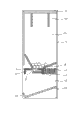
Fig. 1 is a three-dimensional exploded view of the present utility model;
Fig. 2 is a structural representation of the present utility model;
Fig. 3 is the pen state figure that do not get of the present utility model;
Fig. 4 is the pen state figure that gets of the present utility model.
Label declaration
Get a chamber 12 chutes 13
First outlet, 14 second outlets 15
Put pen mouthful 16 lids 17
Lead a plate 18 a retaining bar 19
Push pedal 2 through holes 21
The specific embodiment
As depicted in figs. 1 and 2, be the self-service pen device of getting that the utility model discloses, comprise casing 1, push pedal 2 and spring 3.
The top of casing 1 forms pen-holding cavity 11, below formation is got a chamber 12 and formed chute 13 between two chambeies.Offer on the pen-holding cavity 11 and put pen mouth 16, first outlet 14 that communicates with chute 13 is offered in the bottom of pen-holding cavity 11.Get the top in a chamber 12 and offer second outlet 15 that communicates with chute 13.To get pen more smooth and easy in order to make, and the bottom of pen-holding cavity 11 is skewed, and first outlet 14 is positioned at lowest part.For the ease of management, pen-holding cavity 11 tops also are provided with lid 17.To get pen in order further facilitating, to get 12 bottoms, a chamber and also be provided with and lead a plate 18 and a retaining bar 19.
When the utility model uses, pen is put into the pen-holding cavity 11 of casing 1 from putting pen mouth 16.
As shown in Figure 3, when not getting, push pedal 2 is subjected to spring 3 thrust, and an end of push pedal 2 stretches out outside the casing 1 naturally, and the through hole 21 of push pedal 2 and first outlet 14 are alignd, and one-pen falls into through hole 21.
As shown in Figure 4, when getting, outside casing 1, push push pedal 2, promoting push pedal 2 slides in casing 1, through hole 21 promptly slides in chute 13 together with wherein that pen, when through hole 21 alignd with second outlet 15, that pen in the through hole 21 falls into got a chamber 12, and the user directly gets pen and can use.
The above only is an embodiment of the present utility model, is not to this case design-calculated restriction, and all equivalent variations of doing according to the design key of this case all fall into the protection domain of this case.
Claims (4)
1. the self-service pen device of getting, it is characterized in that: comprise casing, push pedal and spring, the top of casing forms pen-holding cavity, below formation is got a chamber and formed chute between two chambeies, offer on the pen-holding cavity and put pen mouthful and first outlet that communicates with chute is offered in the bottom of pen-holding cavity; second outlet that communicates with chute is offered at the top of getting a chamber; push pedal is slidingly arranged in the chute, and an end of push pedal stretches out casing and spring is set between the other end and the cabinet wall, offers through hole in the push pedal.
2. the self-service pen device of getting as claimed in claim 1, it is characterized in that: the bottom of described pen-holding cavity is skewed, and first outlet is positioned at lowest part.
3. the self-service pen device of getting as claimed in claim 1 is characterized in that: described pen-holding cavity top is provided with lid.
4. the self-service pen device of getting as claimed in claim 1 is characterized in that: the described bottom, chamber of getting is provided with and leads a plate and a retaining bar.
Priority Applications (1)
| Application Number | Priority Date | Filing Date | Title |
|---|---|---|---|
| CN2011201610317U CN202089434U (en) | 2011-05-19 | 2011-05-19 | Automatic pen taking device |
Applications Claiming Priority (1)
| Application Number | Priority Date | Filing Date | Title |
|---|---|---|---|
| CN2011201610317U CN202089434U (en) | 2011-05-19 | 2011-05-19 | Automatic pen taking device |
Publications (1)
| Publication Number | Publication Date |
|---|---|
| CN202089434U true CN202089434U (en) | 2011-12-28 |
Family
ID=45364518
Family Applications (1)
| Application Number | Title | Priority Date | Filing Date |
|---|---|---|---|
| CN2011201610317U Expired - Fee Related CN202089434U (en) | 2011-05-19 | 2011-05-19 | Automatic pen taking device |
Country Status (1)
| Country | Link |
|---|---|
| CN (1) | CN202089434U (en) |
Cited By (3)
| Publication number | Priority date | Publication date | Assignee | Title |
|---|---|---|---|---|
| CN104116568A (en) * | 2014-07-29 | 2014-10-29 | 汕头大学医学院第一附属医院 | Injector storage device |
| CN106136538A (en) * | 2016-07-25 | 2016-11-23 | 林震云 | Automatic chalk box |
| CN110451092A (en) * | 2019-07-17 | 2019-11-15 | 苏州翌恒生物科技有限公司 | A kind of push-press type heparin tube provides device and heparin tube providing method |
-
2011
- 2011-05-19 CN CN2011201610317U patent/CN202089434U/en not_active Expired - Fee Related
Cited By (3)
| Publication number | Priority date | Publication date | Assignee | Title |
|---|---|---|---|---|
| CN104116568A (en) * | 2014-07-29 | 2014-10-29 | 汕头大学医学院第一附属医院 | Injector storage device |
| CN106136538A (en) * | 2016-07-25 | 2016-11-23 | 林震云 | Automatic chalk box |
| CN110451092A (en) * | 2019-07-17 | 2019-11-15 | 苏州翌恒生物科技有限公司 | A kind of push-press type heparin tube provides device and heparin tube providing method |
Similar Documents
| Publication | Publication Date | Title |
|---|---|---|
| CN202089434U (en) | Automatic pen taking device | |
| CN203328113U (en) | Multifunctional wallet | |
| CN104015985A (en) | Novel storage box with inserting plate | |
| CN102398463A (en) | Novel pen container | |
| CN203194879U (en) | Portable sport cup with storage function | |
| CN201484877U (en) | Drawer-type tea box | |
| CN103565134A (en) | Wardrobe with top-layer clothing easy to store and take | |
| CN204218354U (en) | A kind of bookshelf | |
| CN207202340U (en) | A kind of automatic counting coin box | |
| CN201759077U (en) | Bamboo accommodating cabinet for stationery | |
| CN202396977U (en) | Multifunctional combined low stool | |
| CN204242066U (en) | Support of hard disk | |
| CN204363882U (en) | A kind of liftable paper-extracting box | |
| CN203935123U (en) | A kind of Portable sanitation paper is shelved box | |
| CN203321093U (en) | Fingerprint lock with sliding cover structure | |
| CN203709470U (en) | Pen box | |
| CN202319376U (en) | File box with mirror | |
| CN201721224U (en) | Multi-functional pen holder | |
| CN101920621A (en) | Multifunctional office box | |
| CN203158525U (en) | Simple and convenient coffee box | |
| CN203041768U (en) | Daily supply combined barrel for prison | |
| CN201484023U (en) | Multifunctional office box | |
| CN207821287U (en) | A kind of classified saving pot | |
| CN205410061U (en) | Jar of saving that can manual classification | |
| CN202869632U (en) | Electronic balance with drawer |
Legal Events
| Date | Code | Title | Description |
|---|---|---|---|
| C14 | Grant of patent or utility model | ||
| GR01 | Patent grant | ||
| CF01 | Termination of patent right due to non-payment of annual fee |
Granted publication date: 20111228 Termination date: 20170519 |
|
| CF01 | Termination of patent right due to non-payment of annual fee |